Radiator for vehicle / combo cooler fin design

a technology for cooler fins and radiators, which is applied in the direction of heat exchangers, tubular elements, tubular assemblies, etc., can solve the problems of significant reduction of the available construction volume in the engine compartment of a motor vehicle, the possibility of modification, and the air flow experiencing aerodynamic drag, so as to reduce the number of patterns and meet the requirements of high heat transfer performan

Active Publication Date: 2017-05-11
HANON SYST
View PDF7 Cites 0 Cited by
  • Summary
  • Abstract
  • Description
  • Claims
  • Application Information

AI Technical Summary

Benefits of technology

[0031]It is advantageous to have partial areas of two adjacent fins feature the same fin pattern or the same number of patterns. This allows, for instance, for applying the maximum number of patterns on the first partial areas of the fins, whereas in the second and third partial areas of the fins, a reduced number of patterns is provided. The patterns in the second and third partial area may further be divided into two groups.
[0032]It is provided that the first row of pipes and the second row of pipes arranged adjacent to the first row of pipes are part of a first cooling circuit. In case of multi-circuit multi-row heat exchangers, two or more rows of pipes, which may be adjacent to each other, may be united to form a joint cooling circuit. A combination of multiple rows of pipes, for instance to form a cooling circuit of an internal combustion engine, may meet a high heat transfer performance requirement, allowing the heat exchanger to remain a compact and place-saving unit.

Problems solved by technology

An arrangement of two heat exchangers with different performance requirements or heat transfer capacities is laborious since two separate systems must be integrated into the engine compartment, and furthermore, it significantly reduces the available construction volume in the engine compartment of a motor vehicle.
When a heat exchanger is flooded with a fluid such as air, this air flow experiences an aerodynamic drag.
In such multi-circuit and multi-row heat exchangers according to prior art, there is a disadvantage in that the possibilities of modifying, the heat exchangers that are operated independently from each other, to specific performance specifications while maintaining a specified maximum permitted loss of air pressure are limited.

Method used


Image

  • Radiator for vehicle / combo cooler fin design
  • Radiator for vehicle / combo cooler fin design
  • Radiator for vehicle / combo cooler fin design

Examples


Embodiment Construction

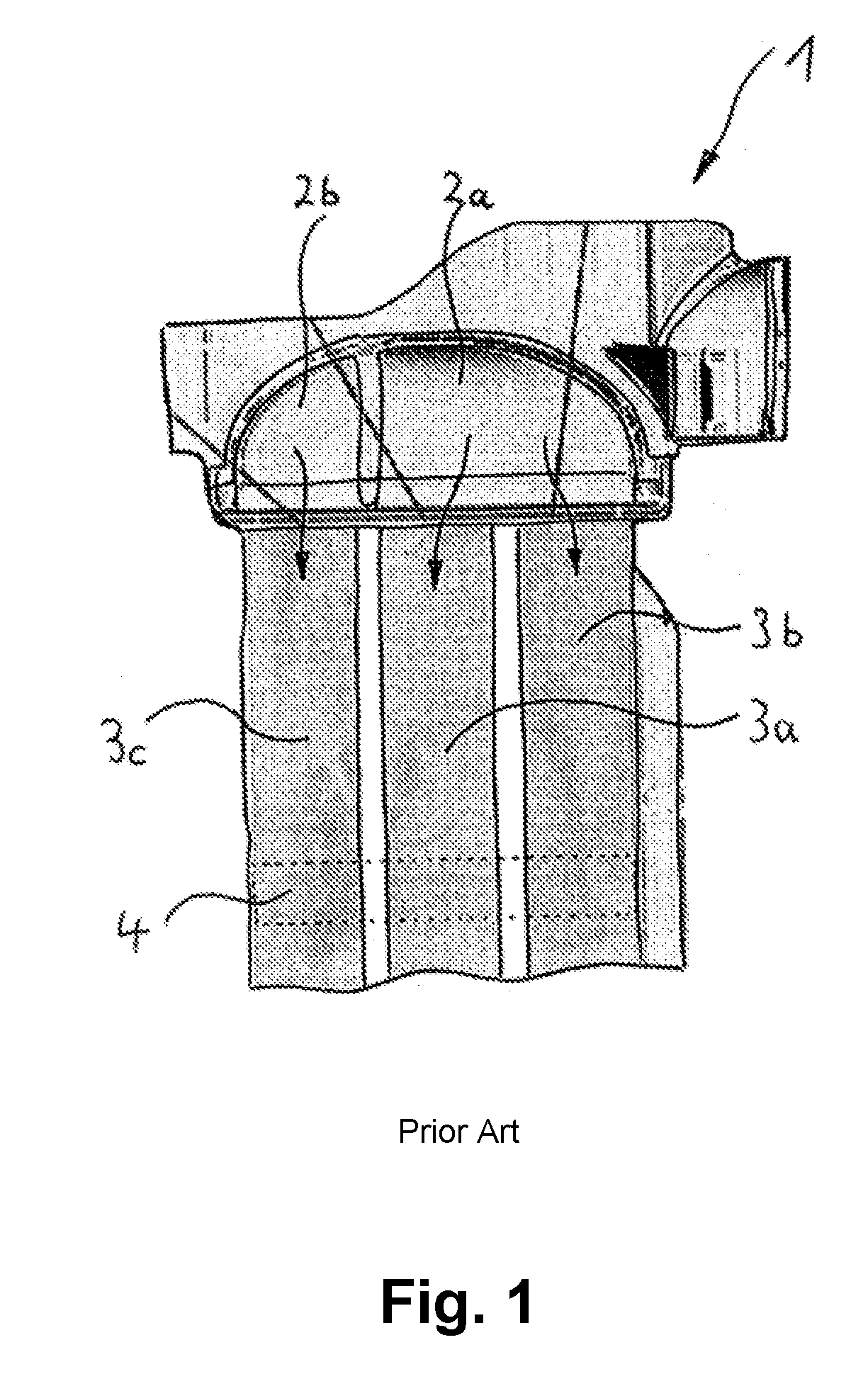
[0041]FIG. 1 shows a segment of a sectional view of a heat exchanger 1 according to prior art. The image shows two inlet tanks 2a and 2b, separated from each other by a bridge, which are flooded by a cooling agent intended for cooling of a first coolant circuit and a second coolant circuit. In the example shown, the first coolant circuit of the heat exchanger 1 may be the cooling circuit for cooling an internal combustion engine, and the second coolant circuit may be a circuit for a charge air cooler.

[0042]The cooling agent of the first cooling circuit, which flows in via the first inlet tank 2a, is distributed over the two shown rows of pipes 3a, 3b of the first coolant circuit, floods them, and is cooled in the process. A first outlet tank positioned downstream from the rows of pipes 3a, 3b, via which the cooled cooling agent of the first coolant circuit exits the heat exchanger 1, is not shown.

[0043]The cooling agent of the second cooling circuit, which flows in via the second in...


PUM


Abstract

A heat exchanger with multiple cooling circuits includes fins featuring at least two adjacent areas, a first one of the areas arranged in a first row of pipes and a second one of the areas arranged in a second row of pipes. A number of patterns are arranged in each of the areas. The number of patterns is determined by a specified heat transfer performance requirement for each of the areas.

Description

CROSS-REFERENCE TO RELATED PATENT APPLICATIONS[0001]This patent application claims priority under 35 U.S.C. §119 to German Patent Application No. 10 2015 119 408.2, filed on Nov. 11, 2015, in the German Intellectual Property Office, the disclosure of which is incorporated herein by reference in its entirety.TECHNICAL FIELD[0002]The invention relates to a heat exchanger with multiple cooling circuits, comprising at least a first and a second row of pipes which are arranged parallel to each other, with multiple cooling pipes arranged in the first and in the second row of pipes, respectively, the cooling pipes being flooded with a fluid intended for cooling associated with the respective cooling circuit, and with fins being arranged between the cooling pipes which are flooded with air and which extend at least across the cooling pipes of two adjacent rows of pipes.BACKGROUND[0003]For the cooling of internal combustion engines used, for instance, in motor vehicles, it is a matter of pri...

Claims


Application Information

Patent Timeline
Patent Type & Authority Applications(United States)
IPC IPC(8): F28F1/32F28F13/14F28D1/04
CPCF28F1/32F28D2021/0094F28F13/14F28D1/0408F28D2021/0082F28F2215/04
Inventor HOFFMANN, CHRISTIANMAHDAL, JOSEFMALOVANY, DANIEL
Owner HANON SYST
Why Eureka
Try Eureka