
Cooking system

a technology of cooking system and temperature-based determination, which is applied in the field of cooking system, can solve the problems of inability to relate the sensed quantities to the use scenario being performed by the user, the use context, and the possibility of high disturbance of the temperature-based determination of the inclination of the prob

Active Publication Date: 2017-06-01
WHIRLPOOL CORP
View PDF24 Cites 30 Cited by
  • Summary
  • Abstract
  • Description
  • Claims
  • Application Information

AI Technical Summary

Benefits of technology

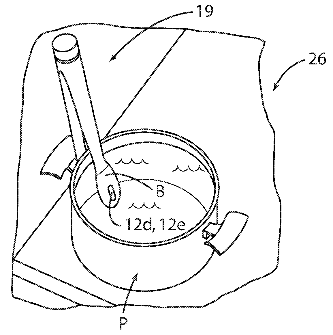
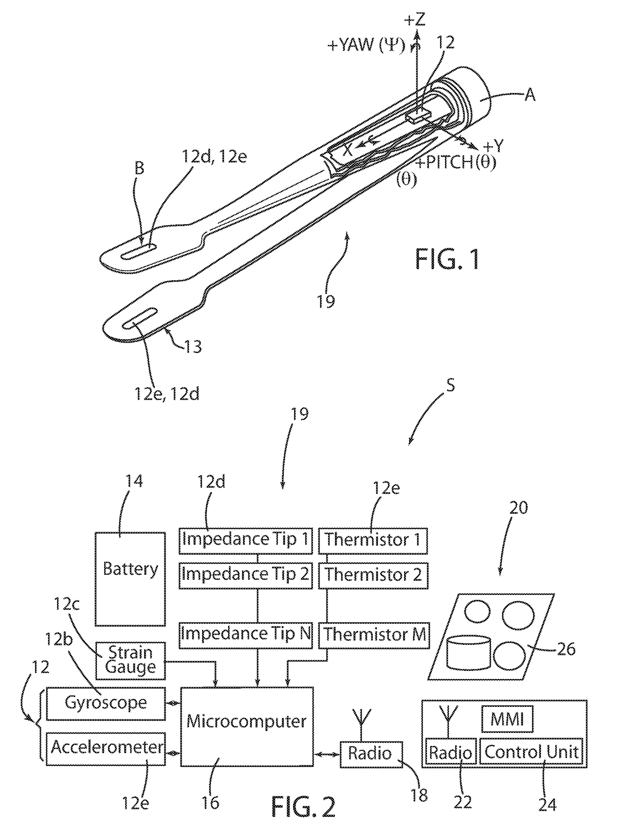
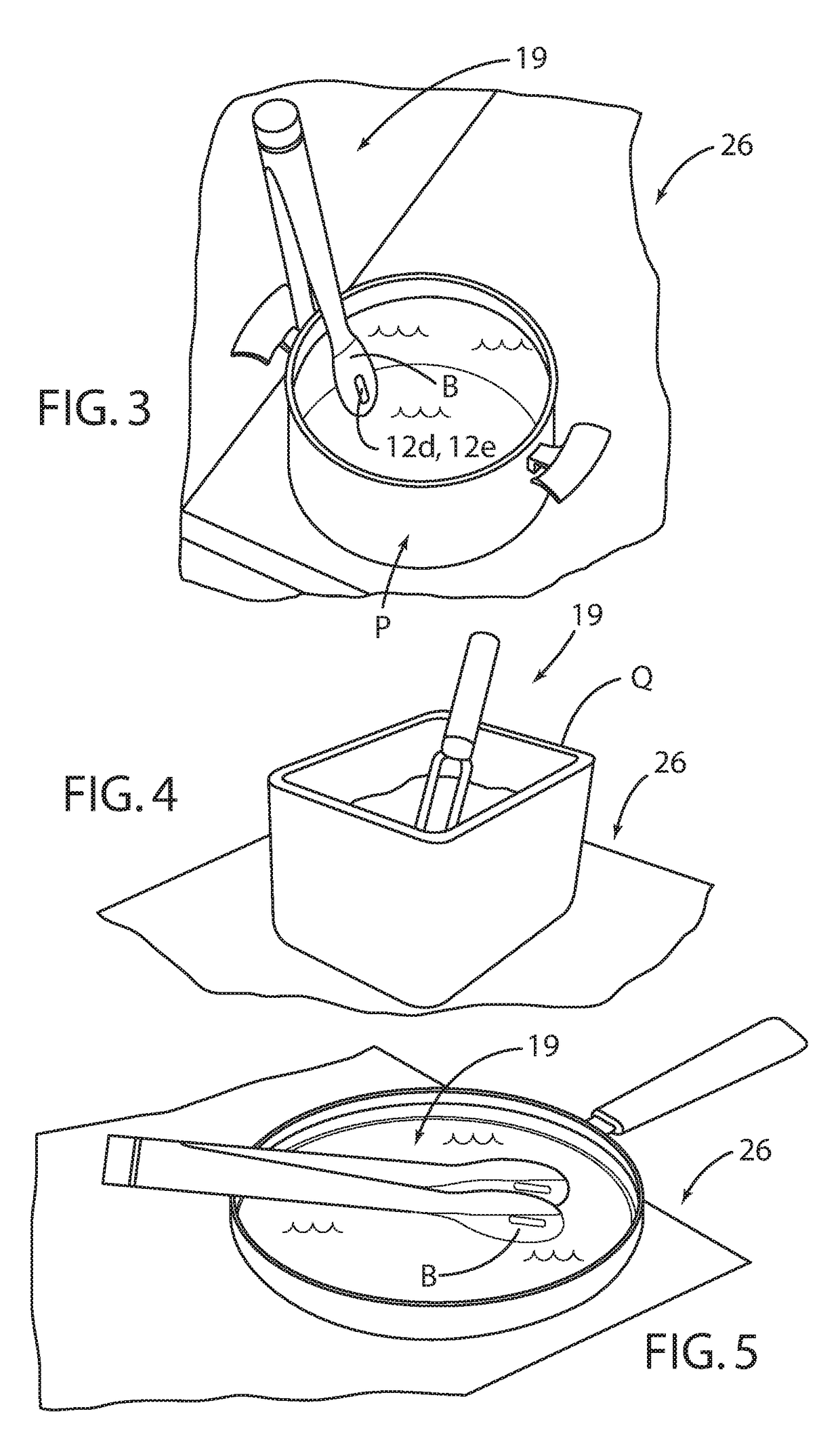
The present invention provides a cooking system using a cooking utensil that can assist the cook in determining the state of the food being cooked by relying on multiple inputs simultaneously and adjusting the cooking output accordingly. The kitchen utensil is equipped with a multi-axis accelerometer and / or gyroscope to assess its context of use, which helps understand which action is being performed with the utensil. The utensil can determine and control the food's cooking state based on physical quantities related to food state, such as temperature and food conductivity, and combining them with probe spatial position and acceleration along multiple axes. This improves the cooking process and makes the cooking utensil more efficient and useful.

Problems solved by technology

One drawback of such temperature probes is that they are not able to determine the actual action being performed with the utensil itself, thus resulting in the inability to relate the sensed quantities to the use scenario being performed by the user (i.e., the use context).
Although the plurality of temperature sensors mitigates the problem of detecting the very core temperature of the food, they all have the drawback of being unable to detect the actual position of the probe with respect to the food, resulting in largely varying results caused by the degree of expertise of the user or cook in correctly placing the probe.
However this temperature-based determination of the probe inclination might be highly disturbed by food anisotropy (i.e., non-uniformity) and spatial gradient in the heat application sources.
Although professional and experienced cooks have developed great skill in inferring the actual cooking state from the aforementioned sensorial inputs, average cooks often struggle with the correct interpretation of such sensorial inputs, thus resulting in poorly prepared meals.

Method used


Image

  • Cooking system
  • Cooking system
  • Cooking system

Examples


Embodiment Construction

[0047]As referenced in the figures, the same reference numerals may be used herein to refer to the same parameters and components or their similar modifications and alternatives. For purposes of description herein, the terms “upper,”“lower,”“right,”“left,”“rear,”“front,”“vertical,”“horizontal,” and derivatives thereof shall relate to the present disclosure as oriented in FIG. 1. However, it is to be understood that the present disclosure may assume various alternative orientations, except where expressly specified to the contrary. It is also to be understood that the specific devices and processes illustrated in the attached drawings, and described in the following specification are simply exemplary embodiments of the inventive concepts defined in the appended claims. Hence, specific dimensions and other physical characteristics relating to the embodiments disclosed herein are not to be considered as limiting, unless the claims expressly state otherwise.

[0048]With reference to the d...


PUM


Abstract

A cooking system includes a kitchen utensil and a cooking hob, wherein the kitchen utensil is provided with one or more sensors arranged on the kitchen utensil. The sensors include acceleration sensors, gyroscopic sensors, and inclination sensors. The cooking appliance is provided with a control unit configured to receive data from the sensors and to elaborate information on how the kitchen utensil is being used, and to control the cooking appliance accordingly.

Description

CROSS-REFERENCE TO FOREIGN PRIORITY APPLICATION[0001]The present application claims the benefit under 35 U.S.C. §119(b) of European Patent Application No. EP 15197107.4 filed Nov. 30, 2015, entitled “Cooking System.”FIELD OF THE INVENTION[0002]The present disclosure relates to a cooking system including a kitchen utensil and a household electrical appliance, particularly a cooking hob, wherein the utensil has sensors that are arranged at the handle of the utensil.BACKGROUND OF THE INVENTION[0003]A utensil having sensors in the handle is disclosed by DE102011080246. In that utensil, infrared sensors are arranged for determining the position of the utensil on the hob by a plurality of fixed infrared beacons provided on the cooking hob.[0004]Other “intelligent” kitchen utensils are known in the art. Such known utensils include lance-shaped thermometers that may be inserted into foodstuff, such as meat and fish, both for pan cooking and for convection ovens. Such lance thermometers come...

Claims


Application Information

Patent Timeline
Patent Type & Authority Applications(United States)
IPC IPC(8): A47J27/00G05B15/02A47J43/28
CPCA47J27/002G05B15/02A47J43/28A47J36/321G01K1/024G01K13/00G01K2207/06A47J43/281A47J43/282A47J43/283A47J43/288A23L5/10
Inventor JOHNCOCK, JAMESMORANDOTTI, ALBERTOPASTORE, CRISTIANO VITO
Owner WHIRLPOOL CORP
Learn More