Liquid ejecting apparatus and pressure-regulating device

Active Publication Date: 2017-06-01
SEIKO EPSON CORP
View PDF5 Cites 14 Cited by
  • Summary
  • Abstract
  • Description
  • Claims
  • Application Information

AI Technical Summary

Benefits of technology

[0031]According to the configuration, it is possible to exhibit the

Problems solved by technology

However, when performing such bonding, creases occur in the flexible film.
In addition, when the flexible film is greatly displaced, bending, or a sta

Method used


Image

  • Liquid ejecting apparatus and pressure-regulating device
  • Liquid ejecting apparatus and pressure-regulating device
  • Liquid ejecting apparatus and pressure-regulating device

Examples


first embodiment

[0055]Hereinafter, a first embodiment of a liquid ejecting apparatus and a pressure-regulating device will be described with reference to drawings.

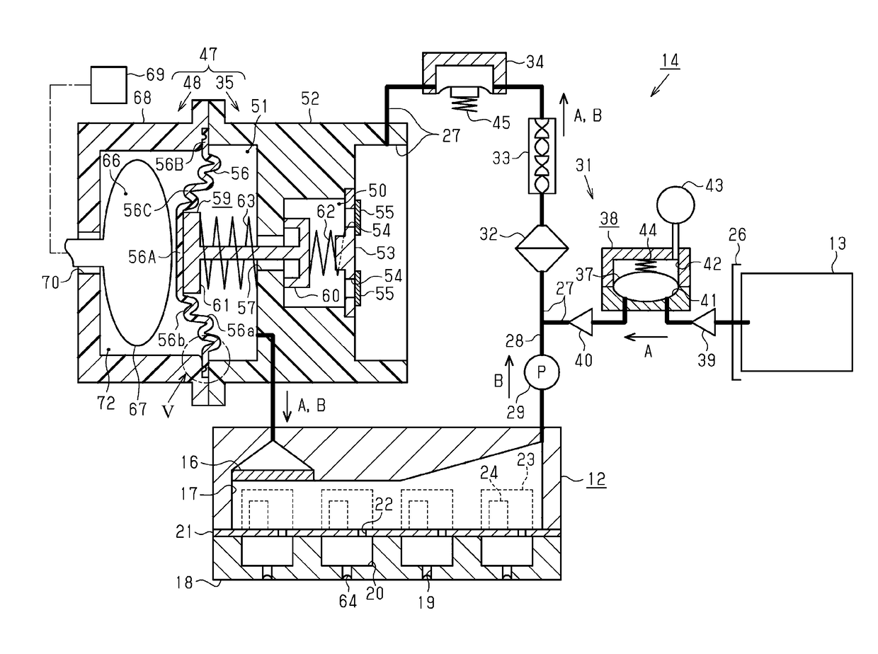
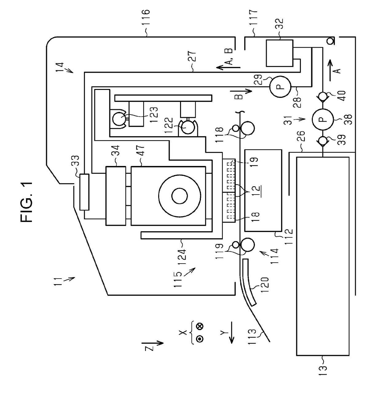
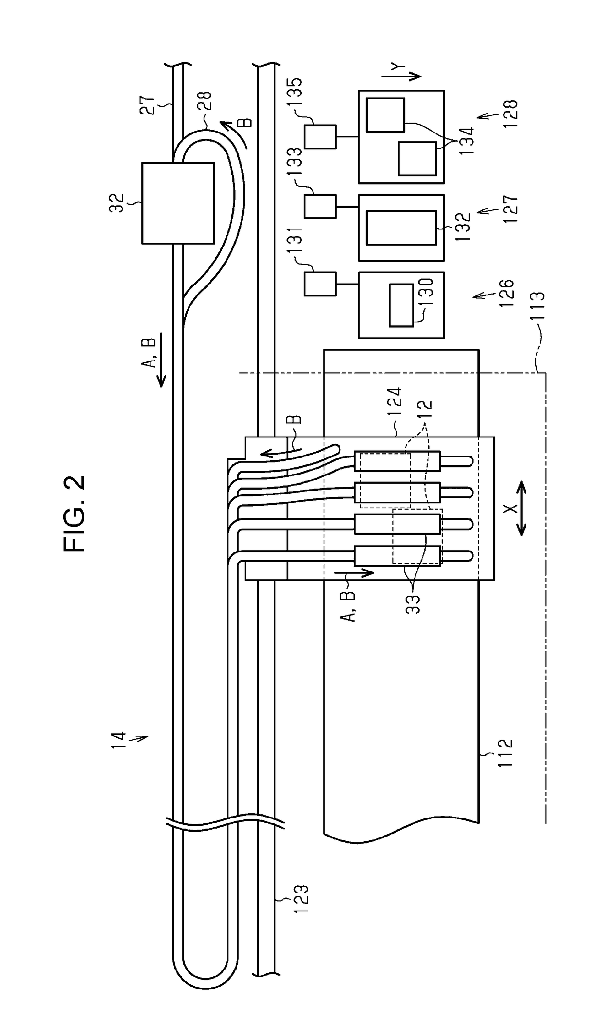
[0056]As illustrated in FIG. 1, a liquid ejecting apparatus 11 is provided with a liquid ejecting unit 12 which ejects liquid, and a supply mechanism 14 which supplies the liquid to the liquid ejecting unit 12 from a liquid supply source 13 which is the supply source of the liquid. In addition, the liquid ejecting apparatus 11 is provided with a supporting table 112 which is disposed at a position facing the liquid ejecting unit 12, a transport unit 114 which transports a medium 113 in a transport direction Y. and a printing unit 115 which performs printing on the medium 113 by moving the liquid ejecting unit 12 in a scanning direction X. The supporting table 112 extends in a width direction (scanning direction X) of the medium 113 which is orthogonal to (intersect) the transport direction Y of the medium 113.

[0057]The supporting table 11...

second embodiment

[0116]Subsequently, a second embodiment of the liquid ejecting apparatus will be described with reference to drawings. A pressurizing mechanism in the second embodiment is different from the case of the first embodiment. Since other features are substantially the same as those in the first embodiment, the same configurations are given the same reference numerals and redundant descriptions will be omitted.

[0117]As illustrated in FIG. 8, the liquid supply source 83 is formed of an outer case 84 which is formed in an airtight state, and a liquid pack 85 which is accommodated in the outer case 84, and can be deformed in a state in which liquid is sealed, and a space between the outer case 84 and the liquid pack 85 is set to a pressurizing chamber 86.

[0118]A pressurizing mechanism 88 pressurizes liquid supplied to the pressure-regulating mechanism 35, by pressurizing the pressurizing chamber 86. That is, the pressurizing mechanism 88 is provided with a pressurizing path 89 which is conne...

third embodiment

[0125]Subsequently, a third embodiment of the liquid ejecting apparatus will be described with reference to drawings. In the third embodiment, the pressure-regulating device is different from those in the first embodiment and the second embodiment. In addition, since other features are substantially the same as those in the first embodiment and the second embodiment, the same configurations are given the same reference numerals and redundant descriptions will be omitted.

[0126]As illustrated in FIG. 9, the liquid supply path 27 is connected to the liquid inflow unit 50 at a position different from the wall section 53 which supports the upstream side biasing member 62 through the filter member 55. In the on-off valve 59, the moving unit 61 and the valve unit 60 are respectively provided, as separate members. The moving unit 61 is integrated with the diaphragm section 56. Specifically, the moving unit 61 is bonded onto the first face 56a side in the pressure receiving portion 56A. In a...


PUM


Abstract

A liquid ejecting apparatus includes a pressure-regulating mechanism which is provided in a liquid supply path in which it is possible to supply liquid to a liquid ejecting unit, and includes a liquid accommodation part which can accommodate the liquid internally, and in which a volume of the liquid accommodation part is changed depending on displacing of a diaphragm section, in which the diaphragm section includes an annular corrugated portion formed in a sectional waveform shape which is deformed when the diaphragm section receives pressure.

Description

BACKGROUND[0001]1. Technical Field[0002]The present invention relates to a liquid ejecting apparatus such as an ink jet printer and a pressure-regulating device which regulates the pressure of liquid in the liquid ejecting apparatus.[0003]2. Related Art[0004]In the related art, ink jet printers which perform printing by ejecting ink (liquid) supplied from an ink tank (liquid supply source) to a medium from an ink jet head (liquid ejecting unit) are known as an example of a liquid ejecting apparatus. There are printers provided with a damper (pressure-regulating device) which regulates the pressure of ink supplied to the ink jet head within such printers (JP-A-2009-178889).[0005]The damper is provided with a pressure varying chamber (fluid chamber) which is partitioned by a flexible film (diaphragm section), and a head side liquid chamber (liquid accommodation unit). In addition, the damper is provided with a tank side liquid chamber (liquid inflow unit) which is connected to the hea...

Claims


Application Information

Patent Timeline
IPC IPC(8): B41J2/175
CPCB41J2/17596B41J2/175B41J2/17509B41J2/16526
Inventor SATO, MASAHIKOMATSUMOTO, KEIJIKIMURA, HITOTOSHI
Owner SEIKO EPSON CORP
Why Eureka
Try Eureka