
Projection-type image display device

Active Publication Date: 2017-06-01
MAXELL HLDG LTD
View PDF2 Cites 10 Cited by
  • Summary
  • Abstract
  • Description
  • Claims
  • Application Information

AI Technical Summary

Benefits of technology

The patent aims to prevent the decrease in visibility of a projection image.

Problems solved by technology

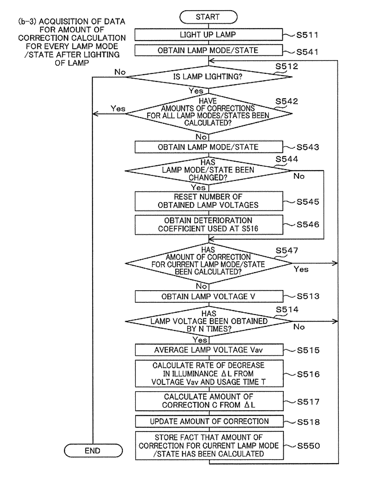
A discharge lamp used for a projection-type image display device has a problem of reduction in image quality such as a contrast of a projected image caused by deterioration in illuminance due to instability of discharge at startup and long-term use.

Method used


Image

  • Projection-type image display device
  • Projection-type image display device
  • Projection-type image display device

Examples


example 1

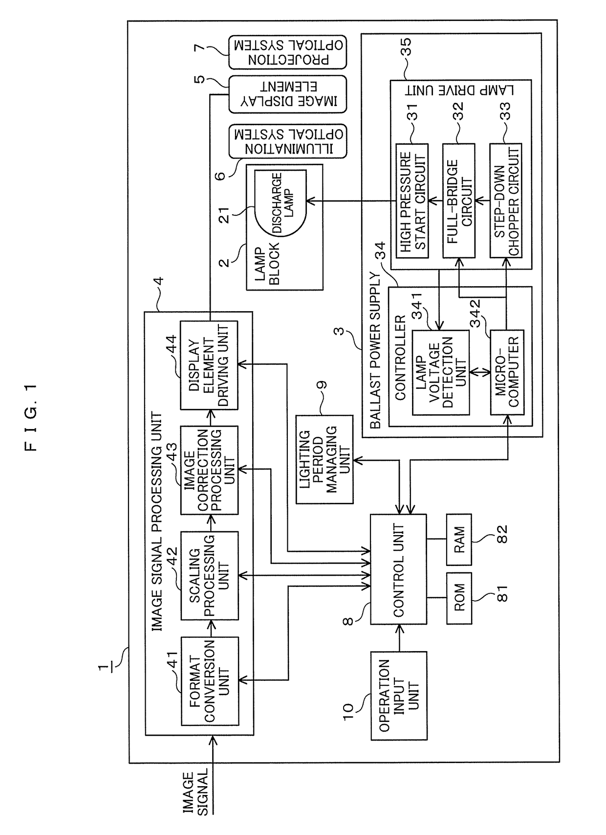
[0027]FIG. 1 is a block configuration diagram illustrating a projection-type image display device according to Example 1. A projection-type image display device 1 includes a lamp block 2, a ballast power supply 3, an image signal processing unit 4, an image display element 5, an illumination optical system 6, a projection optical system 7, a control unit 8, a lighting period managing unit 9, and an operation input unit 10.

[0028]The lamp block 2 houses a discharge lamp 21 such as an ultrahigh pressure mercury lamp, a xenon lamp, and a metal halide lamp serving as a light source.

[0029]The ballast power supply 3 is a circuit to stably supply electric power required to light up a lamp to the discharge lamp 21. The ballast power supply 3 includes a step-down chopper circuit 33, a full-bridge circuit 32, a high pressure start circuit 31, and a controller 34. The step-down chopper circuit 33 sets a lamp voltage appropriate for the discharge lamp 21. The full-bridge circuit 32 performs a co...

example 2

[0116]Example 2 includes a microcomputer in the lamp block 2 of Example 1 to add a function to the projection-type image display device.

[0117]FIG. 6 is a block configuration diagram illustrating the projection-type image display device according to Example 2. Like reference numerals designate corresponding or identical elements described in Example 1 (FIG. 1).

[0118]The following omits a repeated description of operations similar to those of Example 1. The following describes only operations different from those of Example 1.

[0119]A projection-type image display device 1′ newly adds a microcomputer 22 in the lamp block 2. The following designates this as a “second microcomputer” and designates the microcomputer 342 provided in the ballast power supply 3 as a “first microcomputer” for discrimination. The second microcomputer 22 stores identification information (ID) and performance data of the discharge lamp 21, which is housed in the lamp block 2, and can communicate with the control...


PUM


Abstract

This projection-type image display device is provided with: a lamp drive unit that drives a lamp; a lamp voltage detection unit that detects a lamp interelectrode voltage (hereinafter referred to as a lamp voltage); an image correction unit that corrects image qualities of image signals to be supplied to an image display element; and a control unit that controls a correction quantity of the image correction unit on the basis of the lamp voltage detected by means of the lamp voltage detection unit. Consequently, deterioration of visibility of a projection image can be suitably suppressed.

Description

TECHNICAL FIELD[0001]The present invention relates to a projection-type image display device that performs image correction processing according to deterioration in illuminance.BACKGROUND ART[0002]A discharge lamp used for a projection-type image display device has a problem of reduction in image quality such as a contrast of a projected image caused by deterioration in illuminance due to instability of discharge at startup and long-term use. As a technique pertaining to this, Patent Literature 1 discloses a configuration that detects an arc failure between electrodes of a discharge lamp by a lamp voltage detection circuit (lamp current detection circuit) or an optical sensor to control the lamp. Patent Literature 2 discloses a configuration that detects an illuminating light of a lamp by an optical sensor, notifies a state change in the illuminating light, and adjusts a projected state of an image.CITATION LISTPatent Literature[0003]PTL 1: Japanese Patent Application Laid-Open No. ...

Claims


Application Information

Patent Timeline
IPC IPC(8): H04N9/31G03B21/20G09G3/00G06T5/00H04N9/44
CPCH04N9/3191G06T5/00H04N9/44G09G3/002G03B21/2026G09G2354/00G06F3/0483G09G2320/0673G09G2320/08G09G2320/066G09G2320/0233G09G2320/045G09G2320/0626H04N5/74H05B41/2928H05B41/3928H05B47/20Y02B20/00G03B21/2053H04N9/3155H04N9/3182
Inventor NAGATA, ERIKOONODERA, SHINJIMORISHITA, SATOMIOKA, NAOYAIWANAGA, MASAAKI
Owner MAXELL HLDG LTD
Learn More