Rotor blown wing aircraft including a rotor blown wing having at least one selectively controllable control surface and a method of controlling a rotor blown wing aircraft

a technology of a rotor blown wing and a control surface, which is applied in the direction of automatic actuation, instruments, navigation instruments, etc., can solve the problems of limiting the overall operational envelope of the aircraft, and achieve the effect of facilitating a vertical landing

Inactive Publication Date: 2017-06-08
SIKORSKY AIRCRAFT CORP
View PDF12 Cites 55 Cited by
  • Summary
  • Abstract
  • Description
  • Claims
  • Application Information

AI Technical Summary

Problems solved by technology

Aircraft attitudes necessary to maintain position over a desired landing location may exceed landing capabilities, including the aircrafts' design attitude, thereby limiting an overall operational envelope of the aircraft.

Method used


Image

  • Rotor blown wing aircraft including a rotor blown wing having at least one selectively controllable control surface and a method of controlling a rotor blown wing aircraft
  • Rotor blown wing aircraft including a rotor blown wing having at least one selectively controllable control surface and a method of controlling a rotor blown wing aircraft
  • Rotor blown wing aircraft including a rotor blown wing having at least one selectively controllable control surface and a method of controlling a rotor blown wing aircraft

Examples


Embodiment Construction

[0031]A detailed description of one or more embodiments of the disclosed apparatus and method are presented herein by way of exemplification and not limitation with reference to the Figures.

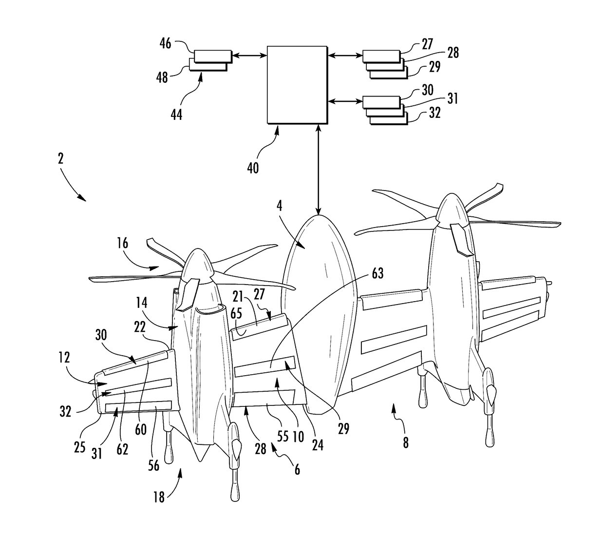
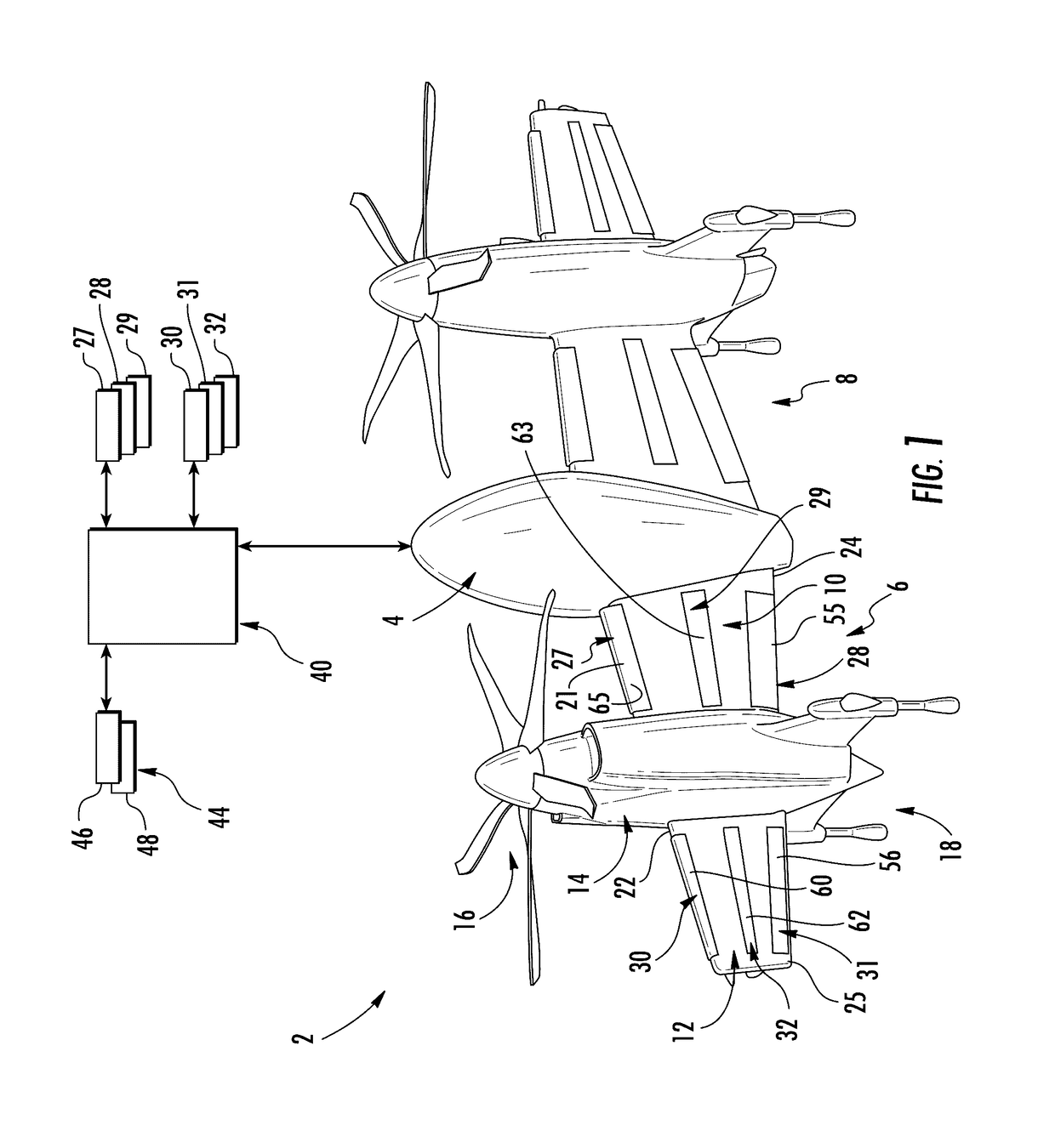
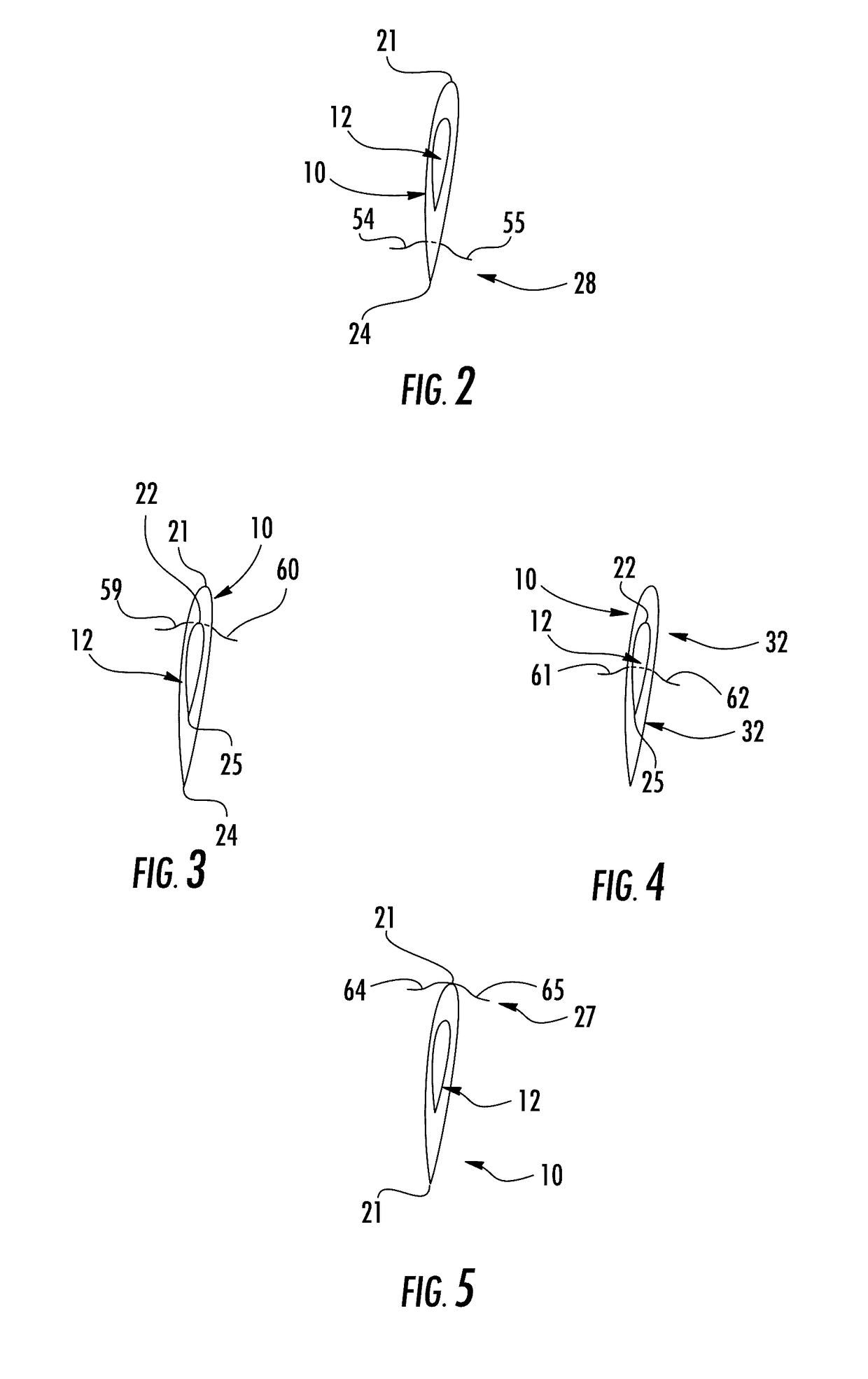
[0032]A rotor blown wing (RBW) aircraft, in accordance with an exemplary embodiment, is indicated generally at 2 in FIG. 1. RBW aircraft 2 includes an airframe 4 that supports a first RBW 6 and a second RBW 8. As each RBW 6 and 8 is substantially similarly constructed, a detailed description will follow with reference to RBW 6 with an understanding that RBW 8 may include similar details. RBW 6 may include a first RBW portion 10 and a second RBW portion 12 separated by a nacelle 14. First RBW portion 10 is arranged inboard of nacelle 14.

[0033]In the exemplary embodiment shown, nacelle 14 supports a rotor 16 as well as a plurality of landing supports indicated generally at 18. As will be appreciated more fully below, it should be understood that RBW aircraft 2 may include a RBW wing uninterrupted b...


PUM


Abstract

A rotor blown wing (RBW) aircraft including an airframe, at least one rotor blown wing (RBW) having at least control selectively controllable surface, at least one rotor configured to generate and direct an airflow over the at least one RBW, and a control system operatively connected to the at least two selectively controllable control surfaces. The control system selectively controls the at least one selectively controllable control surface to change the airflow over the at least one RBW to facilitate a vertical landing.

Description

CROSS REFERENCE TO RELATED APPLICATIONS[0001]This application claims priority to U.S. Provisional Patent Application No. 62 / 246,357, which was filed on Oct. 26, 2015. The entire contents of U.S. Provisional Patent Application No. 62 / 246,357 are incorporated herein by reference.STATEMENT OF FEDERAL SUPPORT[0002]This invention was made with Government support under HR0011-14-C-0010 awarded by the Defense Advanced Research Projects Agency (DARPA). The Government has certain rights in the invention.BACKGROUND[0003]Exemplary embodiments pertain to the art of rotor blown wing aircraft and, more particularly, to a rotor blown wing aircraft including a rotor blown wing having at least one selectively controllable control surface.[0004]Rotor blown wing (RBW) includes at least one wing and one or more proprotors. The proprotors generate a downwash that is passed over the wing to increase net wing lift. Accordingly, a RBW aircraft may hover like a rotary wing aircraft and also fly / cruise on th...

Claims


Application Information

Patent Timeline
Patent Type & Authority Applications(United States)
IPC IPC(8): B64C13/16G01C21/16B64C25/52B64C29/02B64C9/00
CPCB64C13/16B64C29/02G01C21/165B64C25/52B64C9/00
Inventor ALBER, MARK R.PARKHURST, JEFFERYFEGELY, CODYKUBIK, STEPHEN
Owner SIKORSKY AIRCRAFT CORP
Why Eureka
Try Eureka