Measuring respiration rate with multi-band plethysmography

a multi-band plethysmography and respiration rate technology, applied in the field of processing of photoplethysmograms (ppg) signals, can solve the problems of skin and vasculature expanding and contracting, introducing noise to the signal, and compromising the signal

Inactive Publication Date: 2017-06-15
APPLE INC
View PDF8 Cites 49 Cited by
  • Summary
  • Abstract
  • Description
  • Claims
  • Application Information

AI Technical Summary

Benefits of technology

[0004]Further, multiple wavelengths of light may be employed. For various wavelengths, relatively long wavelengths may interrogate relatively deep blood vessels in comparison to relatively short wavelengths, which may interrogate relatively shallow blood vessels. Accordingly, for co-located emitters of different wavelengths, there may be a time delay in the pulse signal measured by each wavelength. For example, green light may interrogate relatively shallow blood vessels near the surface of the skin, and red light may interrogate relatively deep blood vessels deeper beneath the skin, and thus the pulse signal measured by the green light may be delayed in time compared to the pulse signal measured by the red light. The time delay as a function of time may vary according to the constriction and dilation of the blood vessels, which itself may vary according to the respiratory rate of a user. In this way, the light information of various wavelengths may be used to compute such a time delay as a function of time, and a respiratory rate signal may be determined accordingly.

Problems solved by technology

However, the signal may be compromised by noise due to motion artifacts.
That is, movement of the body of a user may cause the skin and vasculature to expand and contract, introducing noise to the signal.
The light information from each sensor may include the same noise signal, and thus subtracting one from the other can result in a heart rate signal where the noise has been canceled out.
Accordingly, for co-located emitters of different wavelengths, there may be a time delay in the pulse signal measured by each wavelength.

Method used


Image

  • Measuring respiration rate with multi-band plethysmography
  • Measuring respiration rate with multi-band plethysmography
  • Measuring respiration rate with multi-band plethysmography

Examples


Embodiment Construction

[0014]In the following description of examples, reference is made to the accompanying drawings which form a part hereof, and in which it is shown by way of illustration specific examples that can be practiced. It is to be understood that other examples can be used and structural changes can be made without departing from the scope of the disclosed examples.

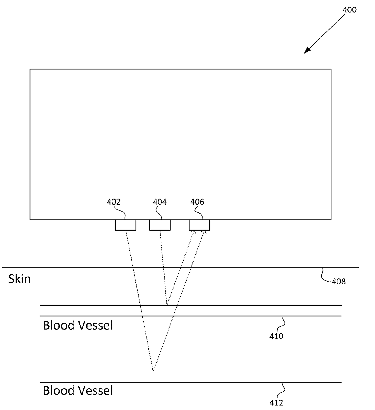
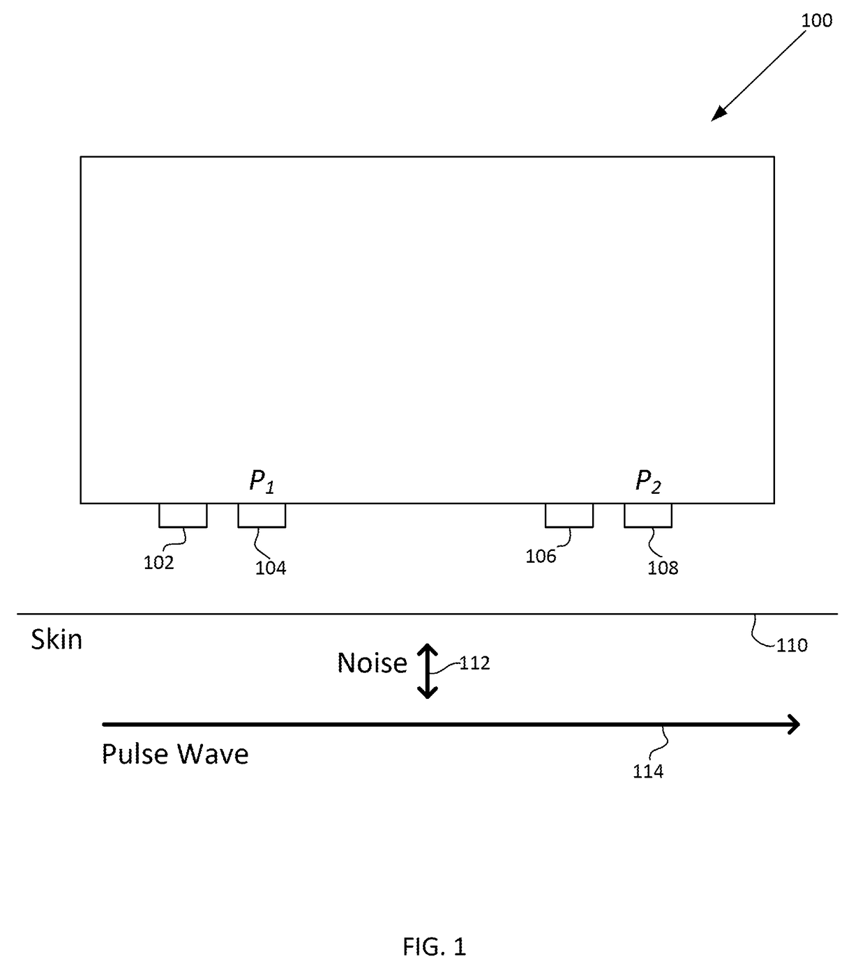
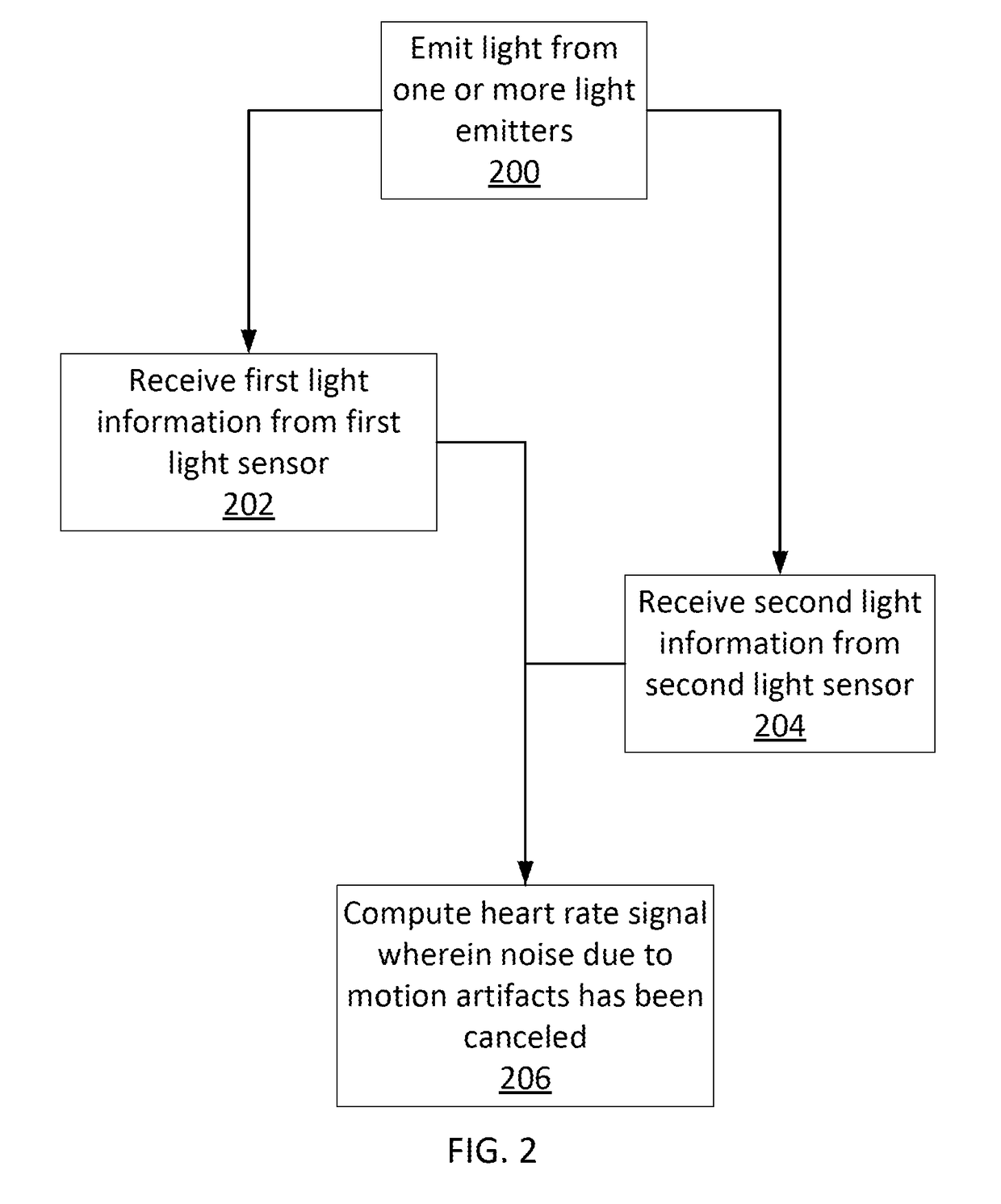
[0015]A photoplethysmogram (PPG) signal may be obtained from a pulse oximeter, which employs a light emitter and a light sensor to measure the perfusion of blood to the skin of a user. However, the signal may be compromised by noise due to motion artifacts. That is, movement of the body of a user may cause the skin and vasculature to expand and contract, introducing noise to the signal. To address the presence of motion artifacts, examples of the present disclosure can receive light information from two light sensors situated in a line parallel to the direction of the blood pulse wave. The light information from each sensor may in...


PUM


Abstract

A photoplethysmogram (PPG) signal may be obtained from a pulse oximeter, which employs a light emitter and a light sensor to measure the perfusion of blood to the skin of a user, and multiple wavelengths of light may be employed. For various wavelengths, relatively long wavelengths may interrogate relatively deep blood vessels in comparison to relatively short wavelengths, which may interrogate relatively shallow blood vessels. Accordingly, for co-located emitters of different wavelengths, there may be a time delay in the pulse signal measured by each wavelength. The time delay as a function of time may vary according to the constriction and dilation of the blood vessels, which itself may vary according to the respiratory rate of a user.

Description

FIELD OF THE DISCLOSURE[0001]This relates generally to processing of a photoplethysmogram (PPG) signal.BACKGROUND OF THE DISCLOSURE[0002]A photoplethysmogram (PPG) signal may be obtained from a pulse oximeter, which employs a light emitter and a light sensor to measure the perfusion of blood to the skin of a user. However, the signal may be compromised by noise due to motion artifacts. That is, movement of the body of a user may cause the skin and vasculature to expand and contract, introducing noise to the signal.SUMMARY OF THE DISCLOSURE[0003]A photoplethysmogram (PPG) signal may be obtained from a pulse oximeter, which employs a light emitter and a light sensor to measure the perfusion of blood to the skin of a user. However, the signal may be compromised by noise due to motion artifacts. That is, movement of the body of a user may cause the skin and vasculature to expand and contract, introducing noise to the signal. To address the presence of motion artifacts, examples of the p...

Claims


Application Information

Patent Timeline
Patent Type & Authority Applications(United States)
IPC IPC(8): A61B5/20A61B5/024A61B5/087
CPCA61B5/205A61B5/02427A61B5/0873A61B5/0205
Inventor CULBERT, DANIEL J.SHAPIRO, IAN R.
Owner APPLE INC
Why Eureka
Try Eureka