Thermo Water

a water supply system and thermoelectric technology, applied in water conservation, refrigeration machines, energy-based wastewater treatment, etc., can solve the problems of inapplicability, inability to operate, and inability to meet the needs of water supply systems of this type, and achieve cost-effective effects

Inactive Publication Date: 2017-06-15
SARIKAYA MAHMUT
View PDF0 Cites 10 Cited by
  • Summary
  • Abstract
  • Description
  • Claims
  • Application Information

AI Technical Summary

Benefits of technology

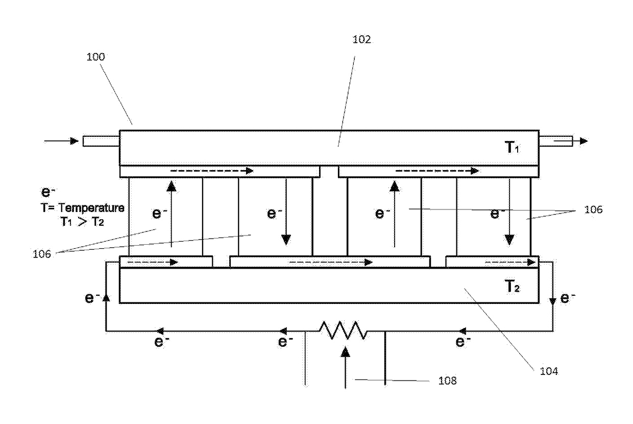
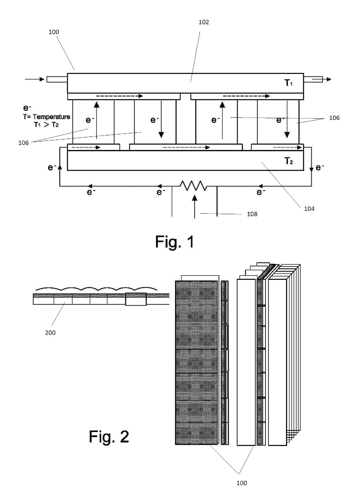
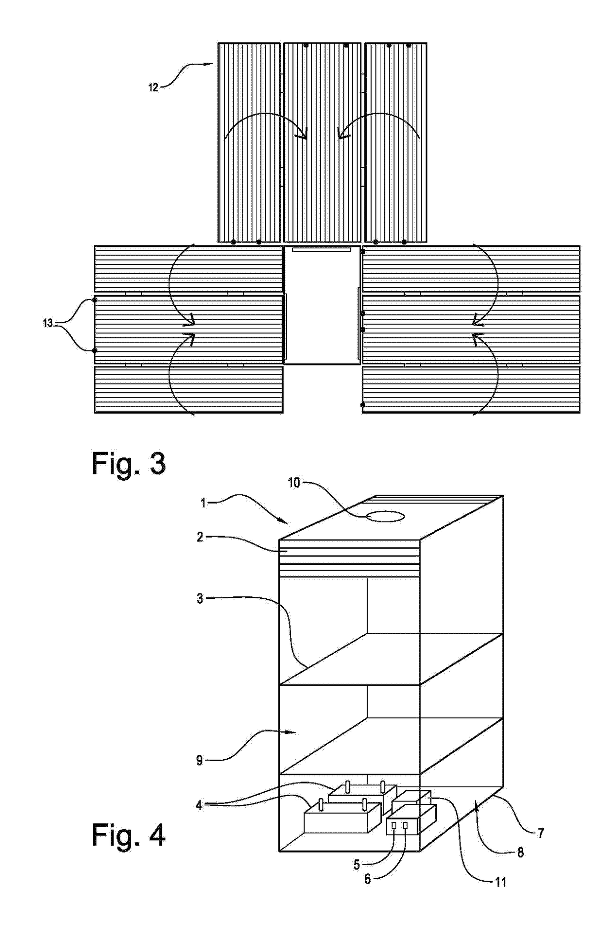
[0006]The present invention is directed to a practical and cost effective water supply system that is capable of turning air humidity into a fresh clean water supply and being powered by nature and / or alternative energy sources. The water supply system can include an air suction device for pulling in air from the surrounding area, an air humidity condensing system that transforms humidity in the pulled in air into water, a water collector for collecting the water generated by the air humidity condensing system, a water treatment system for filtering and disinfecting the collected water, and a water storage tank for storing the treated water. A solar power generator and / or a thermoelectric generator (TEG) can be used to provide the power needed by the water supply system.

Problems solved by technology

There are areas where humidity is high and yet a water supply is scarce.
It is wasteful, especially in the water scarce areas, to let the moisture water collected by the dehumidifiers to be simply dumped or drained away without being utilized.
In certain areas, severe water shortages not only perpetuate the cycle of poverty and misery, but can also lead to malnutrition, even death.
However, a water supply system of this kind needs an electric power supply to operate and would not be practical in the areas where electricity is not available or is very limited and expensive.

Method used


Image

  • Thermo Water
  • Thermo Water
  • Thermo Water

Examples


Embodiment Construction

[0055]The following detailed description is merely exemplary in nature and is not intended to limit the described embodiments or the application and uses of the described embodiments. As used herein, the word “exemplary” or “illustrative” means “serving as an example, instance, or illustration.” Any implementation described herein as “exemplary” or “illustrative” is not necessarily to be construed as preferred or advantageous over other implementations. All of the implementations described below are exemplary implementations provided to enable persons skilled in the art to make or use the embodiments of the disclosure and are not intended to limit the scope of the disclosure, which is defined by the claims.

[0056]It is also to be understood that the specific devices and processes illustrated in the attached drawings, and described in the following specification, are simply exemplary embodiments of the inventive concepts defined in the appended claims. Hence, specific dimensions and o...


PUM

PropertyMeasurementUnit
sizeaaaaaaaaaa
humidityaaaaaaaaaa
air humidityaaaaaaaaaa

Abstract

A water supply system is provided including an air suction device for pulling in air from a surrounding area, an air humidity condensing system for transforming humidity contained in the pulled in air into water, a water collector for collecting the water generated by the air humidity condensing system, a water treatment system for filtering and disinfecting the collected water, and a water storage tank for storing the treated water. The water supply system can further include a power supply system for supplying power needed to operate the water supply system. The power supply system can include a solar power supply system and/or a thermoelectric power supply system.

Description

CROSS-REFERENCE TO RELATED APPLICATION[0001]This application claims the benefit of co-pending U.S. Provisional Patent Application Ser. No. 62 / 386,904 filed Dec. 15, 2015, which is incorporated herein in its entirety.FIELD OF THE INVENTION[0002]The present invention relates generally to water supply systems, and more particularly, to a water supply system that supplies water utilizing air humidity and nature and / or alternative energy sources.BACKGROUND OF THE INVENTION[0003]There are areas where humidity is high and yet a water supply is scarce. Dehumidifiers can be used in these areas to remove humidity from the air. A dehumidifier typically includes a fan that pulls in air from the surrounding area, which typically has a high moisture level. As the air passes through the dehumidifier, it comes into contact with the dehumidifier's cooling coils, which use condensation to pull moisture from the air by lowering the temperature. This de-moisturized air is then reheated and redistribute...

Claims


Application Information

Patent Timeline
Patent Type & Authority Applications(United States)
IPC IPC(8): E03B3/28H01L35/28F24F3/14F25B21/04C02F1/32C02F1/44C02F1/00B01D46/00E03B11/10B01D5/00
CPCE03B3/28C02F2201/009H01L35/28F24F3/1405B01D5/0027B01D5/0072B01D5/009B01D5/0042C02F1/325C02F1/441C02F1/001B01D46/0032F25B21/04C02F2303/04E03B11/10B01D3/346B01D5/006F25B2321/0212C02F1/048C02F1/14C02F1/16C02F1/283C02F1/32C02F1/78C02F9/00C02F2303/10C02F2303/24C02F2305/08Y02W10/30Y02A20/212Y02A20/00H10N10/10
Inventor SARIKAYA, MAHMUT
Owner SARIKAYA MAHMUT
Why Eureka
Try Eureka