
Gravity feed water treatment system

Active Publication Date: 2011-12-15
ACCESS BUSINESS GRP INT LLC
View PDF10 Cites 61 Cited by
  • Summary
  • Abstract
  • Description
  • Claims
  • Application Information

AI Technical Summary

Benefits of technology

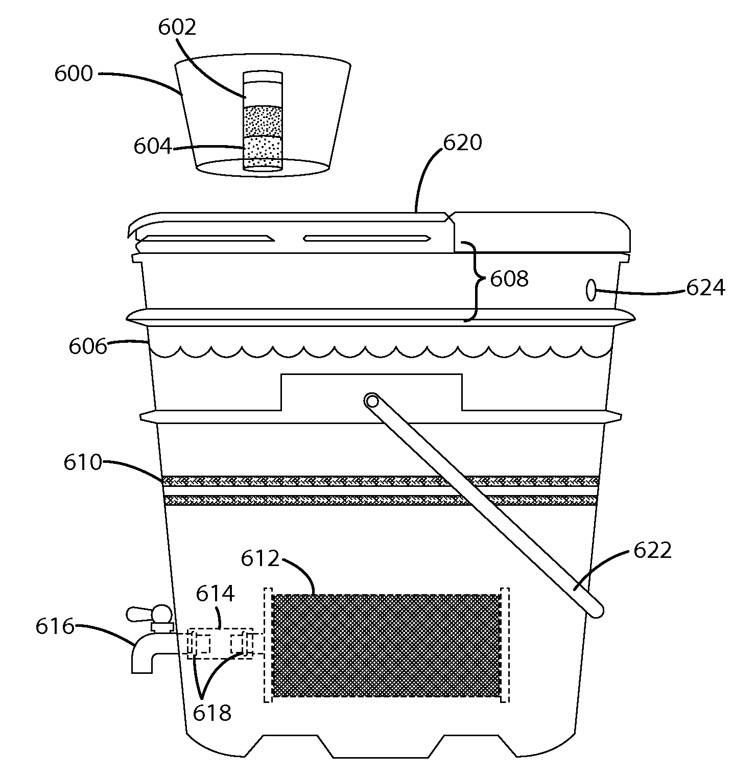
[0015]In another embodiment of the disclosure a water treatment system includes a chlorinator device attached outside of the bucket instead of being attached to the lid of the bucket. A user can access the chlorinator device without otherwise disturbing the water treatment system or having to touch the water in the system. Portions of the chlorinator device may be see-through allowing a user to see how much of the chlorine tablet is left without opening or accessing the chlorinator device.

Problems solved by technology

In many cases, high costs prohibit these operations.
Further, in many locales where water is very scarce, the population is unable to purchase water for consumption due to their low income levels and the fact that municipally treated water is unavailable.
If available, treatment is typically limited to simple pour-through screening or sand filtration.
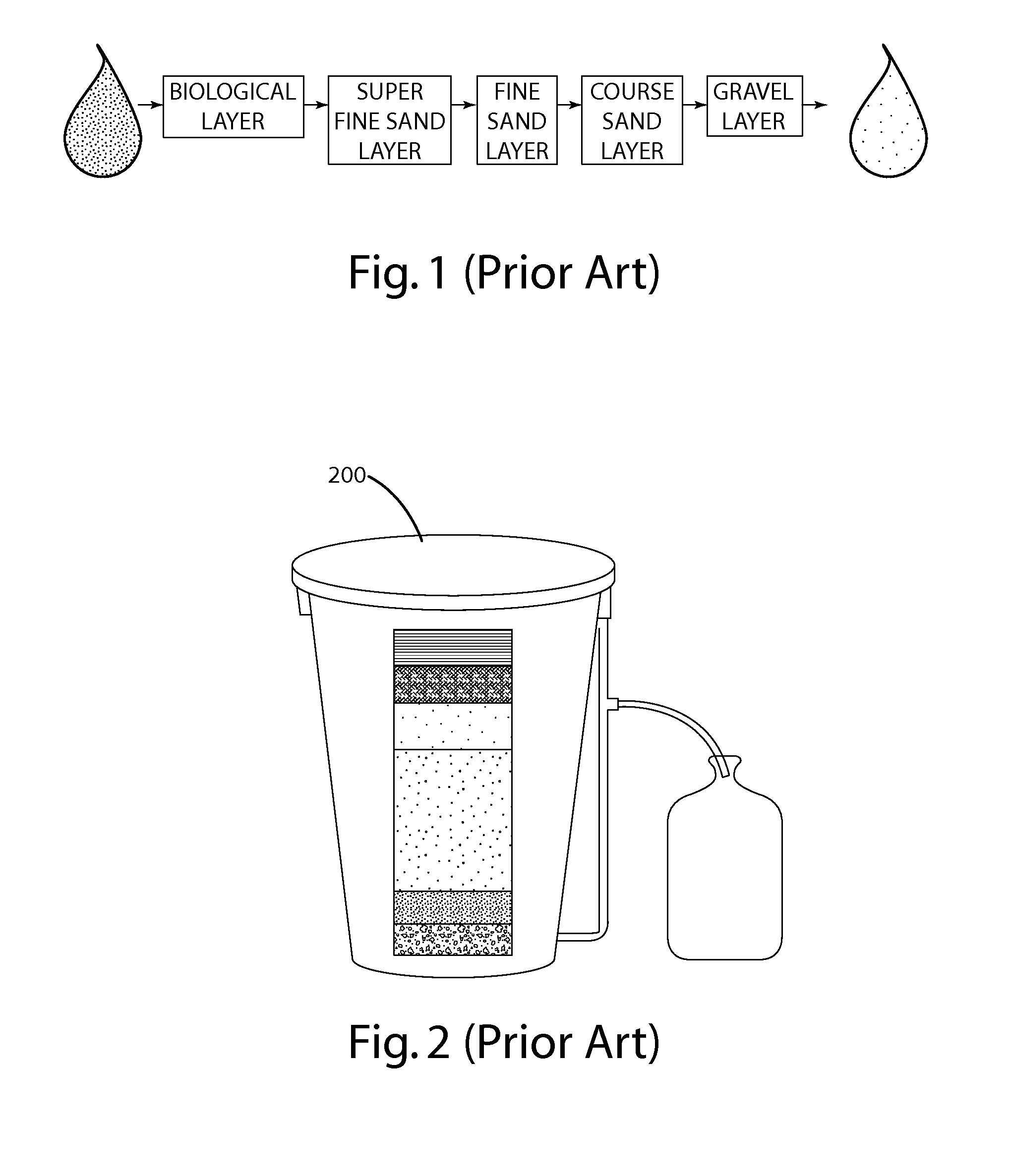
The bio-sand filters commonly used in residential and small village settings tend to be large and heavy.
However, these systems tend to act as a chromatographic column meaning particles are trapped at various rates as the water moves down the column.
The result is that eventually fine particles (thought to be trapped in the sand) begin to break through into the effluent water.
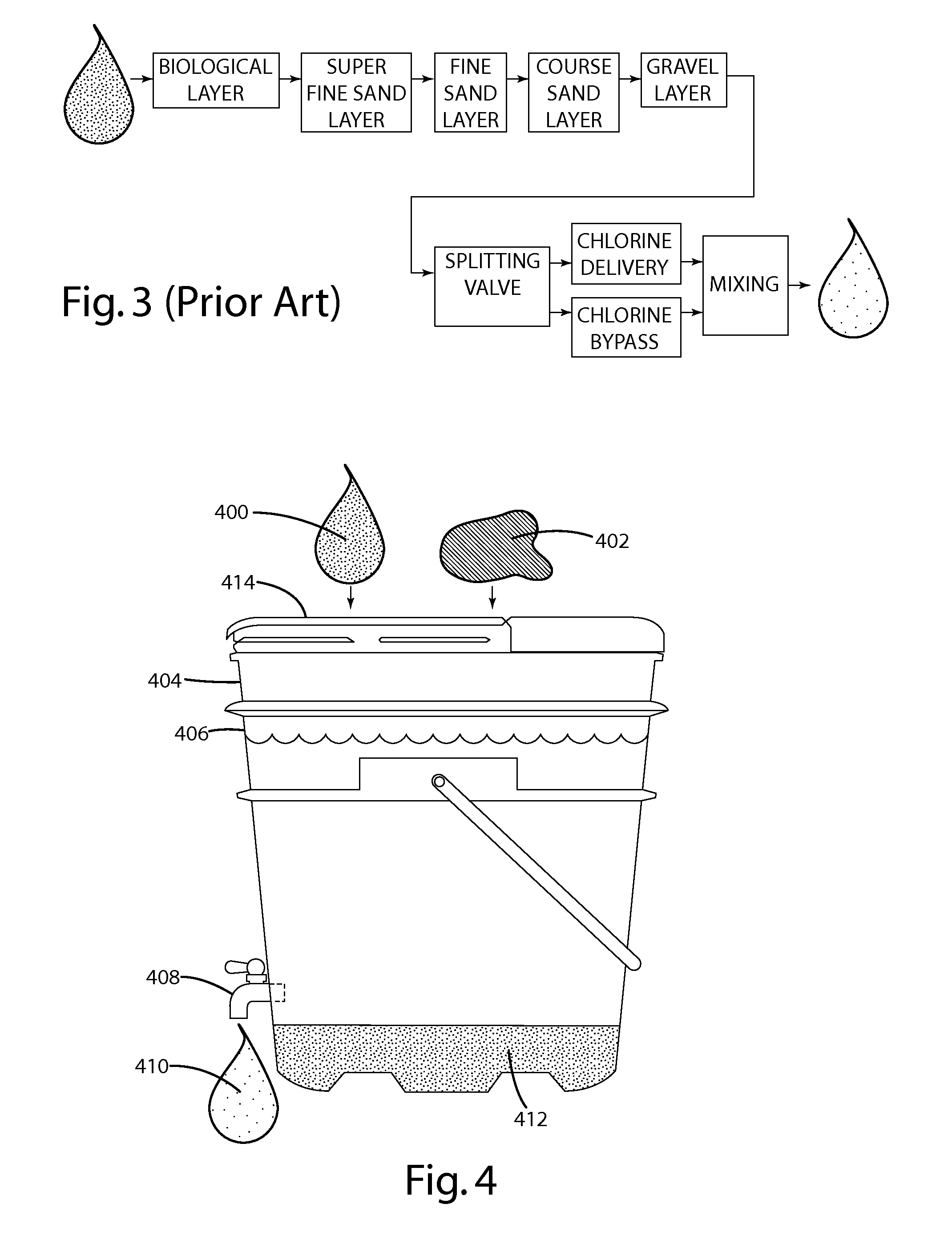
However, the water, even after this treatment, still needs to be disinfected, destroying microbes.
These are less effective than boiling water, with the possibility of the resulting water still containing harmful microbes.
But, the unfamiliarity of the taste chlorine adds to the water, combined with the unit volume required to achieve an effective treatment, leads many users to discontinue using the chlorinated water due to the offensive taste.
As a result, these users often return to using untreated water, which perpetuates the cycle of illness and poor health.
It can be seen from the calculation that the flow rate is fairly slow and may not be acceptable to users accustomed to faster flow rates when drawing water for cooking or drinking.

Method used


Image

  • Gravity feed water treatment system
  • Gravity feed water treatment system
  • Gravity feed water treatment system

Examples


Embodiment Construction

[0068]The POU water treatment system of the present disclosure is configurable to a variety of situations. The various components can be used singly or in various combinations to treat water for consumption or other uses. It is important to note that the configurations detailed below are exemplary and not exhaustive.

[0069]The illustrations of the embodiments described herein are intended to provide a general understanding of the structure of the various embodiments. The illustrations are not intended to serve as a complete description of all of the elements and features of apparatus and systems that utilize the structures or methods described herein. Many other embodiments may be apparent to those of skill in the art upon reviewing the disclosure. Other embodiments may be utilized and derived from the disclosure, such that structural and logical substitutions and changes may be made without departing from the scope of the disclosure. Additionally, the illustrations are merely repres...


PUM

PropertyMeasurementUnit
Fractionaaaaaaaaaa
Fractionaaaaaaaaaa
Fractionaaaaaaaaaa

Abstract

A portable water treatment system includes at least one sub-system to treat water including a flocculation system, a chlorination system, and a bio-sand filter system. The water treatment system may include multiple sub-systems for treating water that feed into one another. The sand filter system may include a mini bio-sand filter, a foam filter, or a pressed block filter. The flocculation system may include a tank bottom that urges settling particles toward a sump and a ladle that removes settled particles. A manual pump or siphon may be included in the water treatment system.

Description

[0001]The present disclosure relates to water treatment systems, and in particular, the disclosure relates to gravity feed water treatment systems.BACKGROUND OF THE INVENTION[0002]As the world's population increases, the demand for water also increases. Indeed, in some parts of the world where the local population is growing at a much higher rate than average, the availability of safe drinking water is lower than average. Some of this situation can be attributed to geography, whether from an arid climate or simply the lack of fresh surface water suitable for drinking. Additionally, many wellheads are running dry due to the lowering of underground aquifers, resulting in new wells being drilled to deeper depths, in an attempt to find water. In many cases, high costs prohibit these operations. Further, in many locales where water is very scarce, the population is unable to purchase water for consumption due to their low income levels and the fact that municipally treated water is unava...

Claims


Application Information

Patent Timeline
IPC IPC(8): C02F1/00C02F1/52C02F9/00C02F1/76C02F1/28C02F1/68
CPCC02F1/003C02F1/281C02F2303/185C02F2303/16C02F2301/043C02F2209/40C02F1/283C02F1/52C02F1/688C02F1/76C02F3/06C02F9/00C02F2103/002C02F2201/006C02F3/04C02F1/001Y02W10/10C02F9/20C02F2101/103
Inventor KUENNEN, ROY W.LAUTZENHEISER, TERRY L.TAYLOR, JR., ROY M.STONER, JR., WILLIAM T.CONRAD, KENNETH E.VANDERKOOI, KAREN J.BEALS, BRIAN S.SCHAMPER, RYAN D.
Owner ACCESS BUSINESS GRP INT LLC
Learn More