Positive exhalation pressure device

a technology of exhalation pressure and positive exhalation chamber, which is applied in the direction of inhalators, medical devices, other medical devices, etc., can solve the problems of obviating the risk of microbiological contamination associated with more complicated (multi-use) devices of the prior ar

Active Publication Date: 2017-06-22
SOLOPEP LTD
View PDF4 Cites 9 Cited by
  • Summary
  • Abstract
  • Description
  • Claims
  • Application Information

AI Technical Summary

Benefits of technology

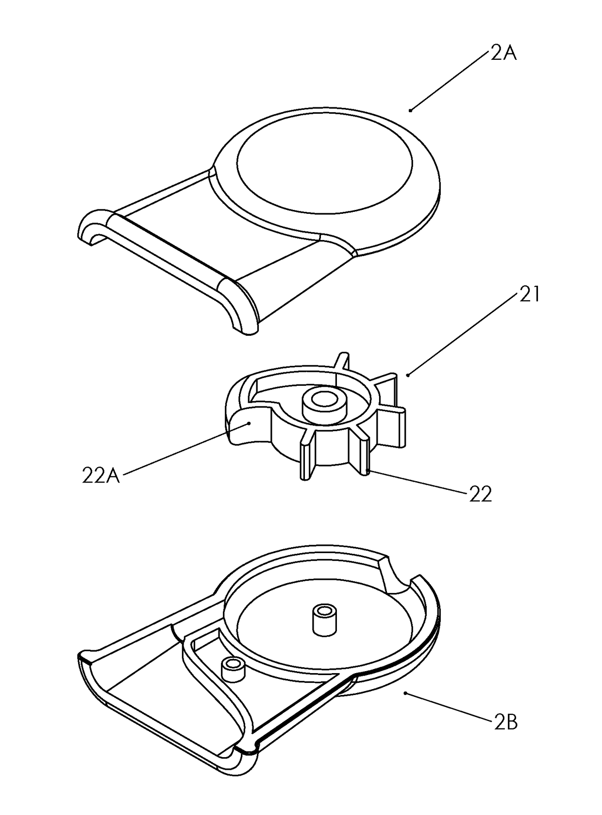
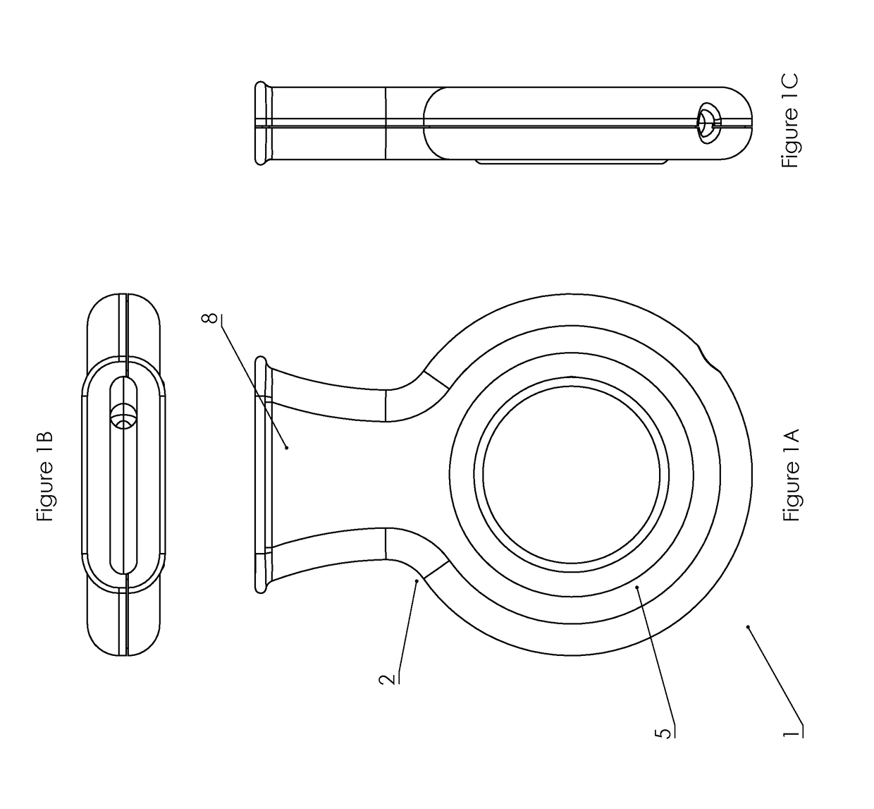
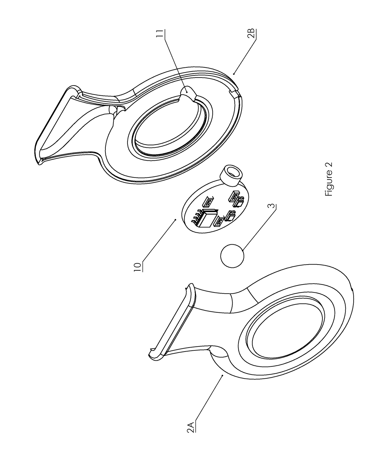
[0008]The device according to the invention provides an uncomplicated and easy-to-manufacture device configured to administer positive exhalation pressure (PEP) therapy to a patient by producing cyclical fluctuations of airflow resistance in response to a patient exhaling through the device. Due to the uncomplicated construction of the device, the device may be manufactured as a single-use device, which obviates the requirement of prior art devices of cleaning of the device, and also obviates the microbiological risk associated with more complicated (multi-use) devices of the prior art. The cyclical fluctuations are primarily determined by the size of the ball and annular track (and consequently the clearance between the ball and walls of the annular track), and these can be easily varied during manufacture to provide devices for a specific clinical situation, for example by varying the diameter of the track, or the clearance between the ball and the track, which can be configured to vary the frequency or rotation of the ball around the track, the average resistance to airflow and peak resistance to airflow.
[0022]In one embodiment, the movable body and air inlet are configured such that the movable body does not block the air inlet as it passes the air inlet. This is easily achieved by, for example, making the air inlet large relative to the size of the movable body.
[0042]In one embodiment, through single use the device avoids provision of a location / space / environment / physical space that can harbour patient-derived microorganisms.
[0043]In one embodiment, the device avoids provision of a reservoir of patient-derived microorganisms.

Problems solved by technology

Due to the uncomplicated construction of the device, the device may be manufactured as a single-use device, which obviates the requirement of prior art devices of cleaning of the device, and also obviates the microbiological risk associated with more complicated (multi-use) devices of the prior art.

Method used


Image

  • Positive exhalation pressure device
  • Positive exhalation pressure device
  • Positive exhalation pressure device

Examples


Embodiment Construction

[0076]All publications, patents, patent applications and other references mentioned herein are hereby incorporated by reference in their entireties for all purposes as if each individual publication, patent or patent application were specifically and individually indicated to be incorporated by reference and the content thereof recited in full.

[0077]Definitions and General Preferences:

[0078]Where used herein and unless specifically indicated otherwise, the following terms are intended to have the following meanings in addition to any broader (or narrower) meanings the terms might enjoy in the art:

[0079]Unless otherwise required by context, the use herein of the singular is to be read to include the plural and vice versa. The term “a” or “an” used in relation to an entity is to be read to refer to one or more of that entity. As such, the terms “a” (or “an”), “one or more,” and “at least one” are used interchangeably herein.

[0080]As used herein, the term “comprise,” or variations ther...


PUM


Abstract

A positive exhalation pressure device (1) is described. The device (1) comprises a housing (2) having an annular chamber (5), a chamber inlet (6) configured to permit air into the chamber, a chamber outlet (7) configured to permit air out of the chamber, and a mouthpiece (8) in fluid communication with the chamber inlet. A movable body such as a ball (3) is disposed in the housing within the annular chamber and configured to revolve around the annular chamber in response to flow of air through the chamber from the chamber inlet to the chamber outlet. The movable body is configured to at least partially block the chamber outlet as it revolves around the annular chamber causing cyclical fluctuations in airflow resistance.

Description

BACKGROUND TO THE INVENTION[0001]Positive Exhalation Pressure (PEP) therapy is used to mobilise secretions and treat atelectasis. Cough and other airway clearance techniques are essential components when the therapy is intended to mobilise secretions. During PEP therapy, the patient exhales against a fixed orifice resistor or a threshold resistor, generating pre-set pressures in the range of 10-20 cm H2O. These expiratory pressures may combat atelectasis by splinting open terminal airways and collapsible alveoli. The splinting of small airways also aids in mobilisation of secretions that may be trapped or plugged due to airway closure.[0002]Several commercial devices are available for PEP therapy, known as PEP devices. These generally have a fixed orifice resistor or threshold resistor capable of developing pressures of 10-20 cm H2O. Some devices incorporate a “flutter” valve to produce oscillation during exhalation, which may further enhance secretion mobilisation. One such device ...

Claims


Application Information

Patent Timeline
Patent Type & Authority Applications(United States)
IPC IPC(8): A61M16/00A61M16/20
CPCA61M16/0006A61M16/208A61M2206/20A61M2205/582A61M2205/33A61M2205/502A61M2205/581A61M2205/0205A61M2205/59A61M15/0008A61M16/0866A61M16/161A61M15/0018A61M15/0098
Inventor O'SULLIVAN, KEVIN J.O'SULLIVAN, LEONARD W.DUNNE, COLUMLINNANE, BARRYMCGRATH, DEIRDRE
Owner SOLOPEP LTD
Why Eureka
Try Eureka