

Pneumatic Tire
- Summary
- Abstract
- Description
- Claims
- Application Information
AI Technical Summary
Benefits of technology
Problems solved by technology
Method used
Image

Examples
embodiment 1
Additional Embodiment 1
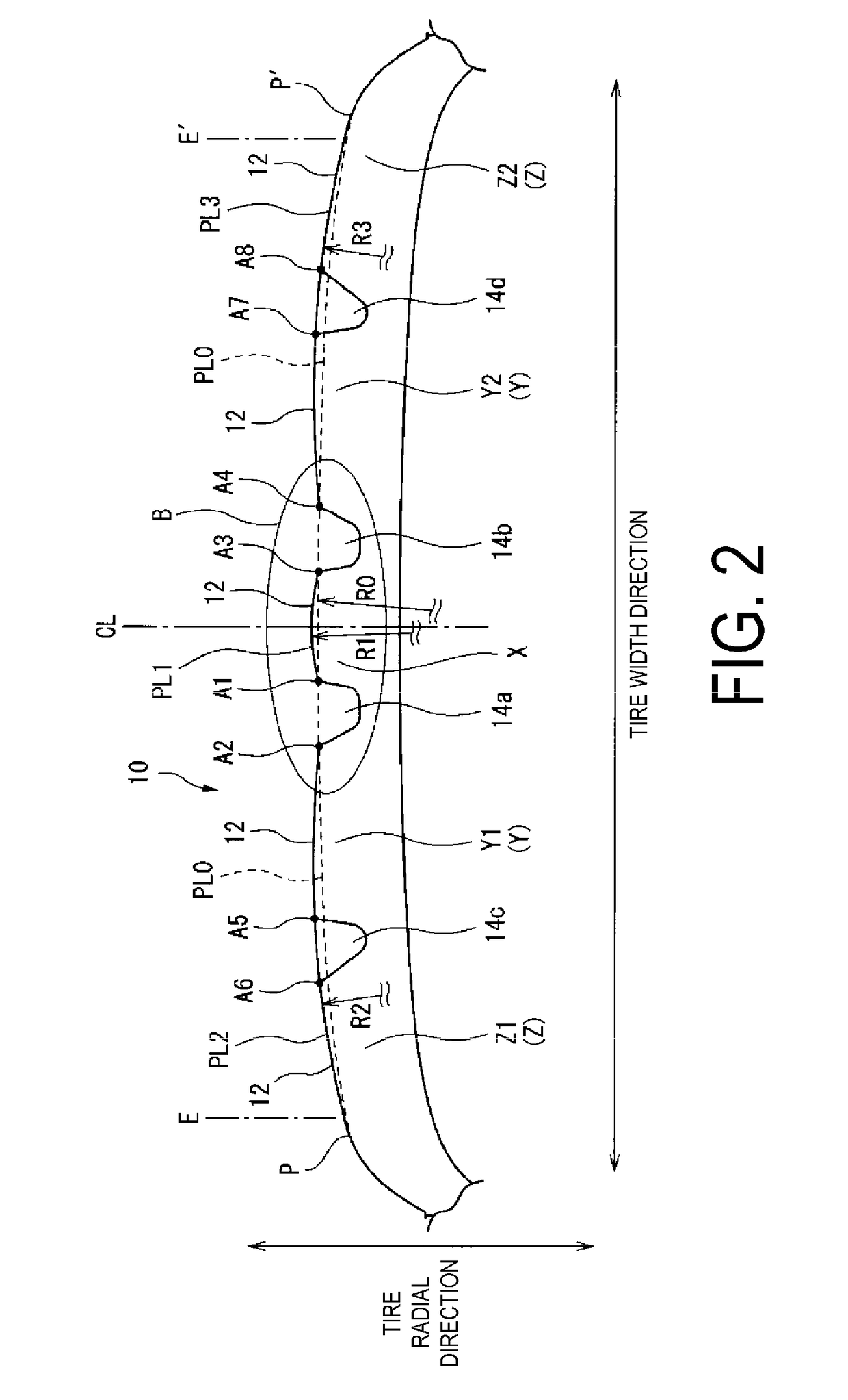
[0048]In the Basic Embodiment, the profile line PL1 of the center land portion X illustrated in FIG. 2 preferably has a maximum protruding amount outward in the tire radial direction with respect to the standard profile line PL0 of from 0.2 to 0.5 mm (Additional Embodiment 1).
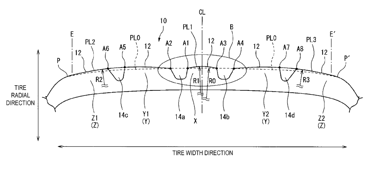
[0049]FIG. 4 is an enlarged view of the circled area B of FIG. 2. In the present embodiment, as illustrated in FIG. 4, the profile line PL1 of the center land portion X has a maximum protruding amount S1 outward in the tire radial direction with respect to the standard profile line PL0. The maximum protruding amount S1 is the maximum dimension in the tire radial direction from the standard profile line PL0 to the profile line PL1.
[0050]When the maximum protruding amount S1 is 0.2 mm or greater, in the center land portion X, the ground contact pressure at approximately the center position in the tire width direction can be made even closer to the ground contact pressure at both outer posit...
embodiment 2
Additional Embodiment 2
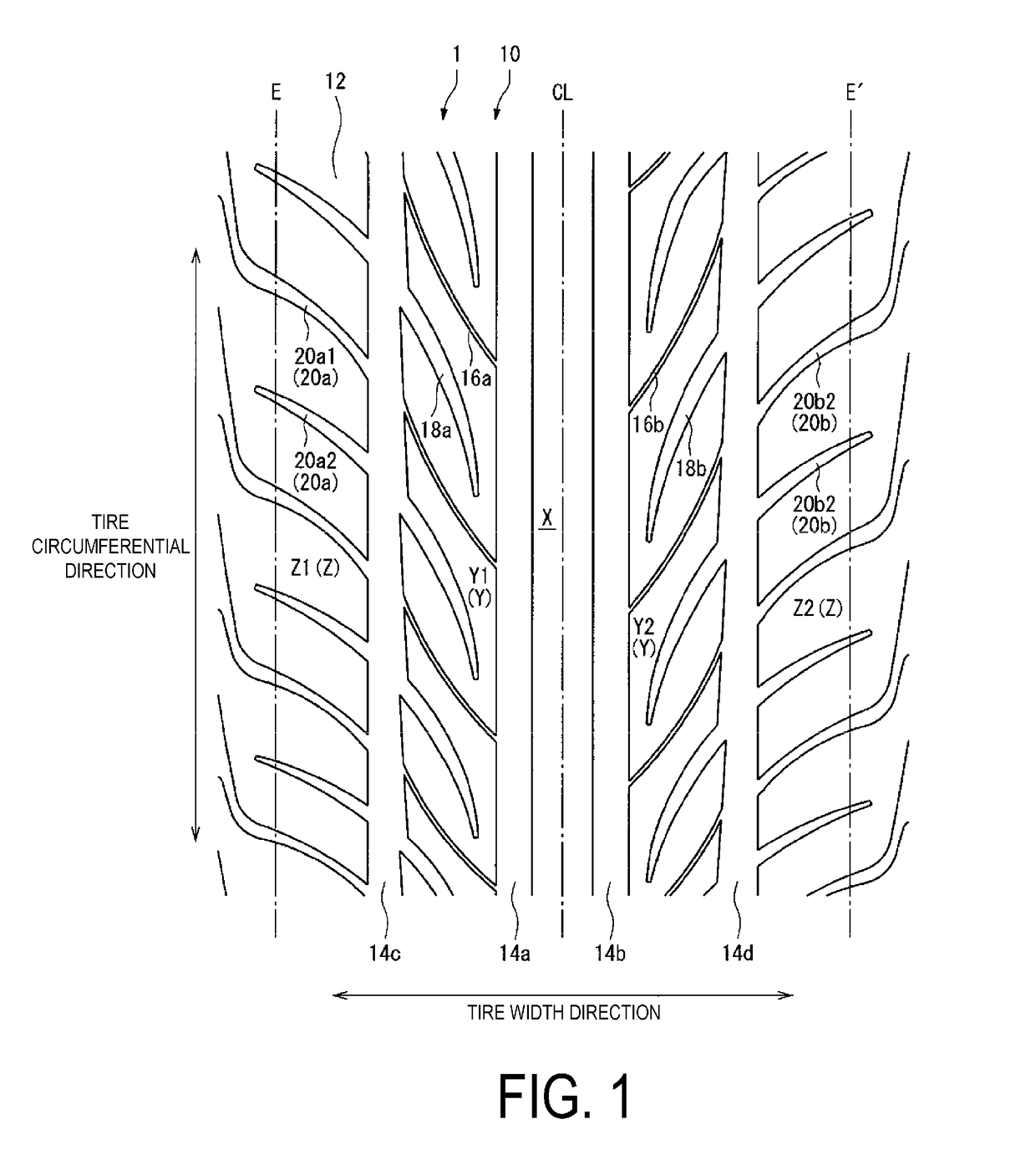
[0053]FIG. 5 is a tire meridian cross-sectional view of a modified example of the example illustrated in FIG. 2. In other words, the example illustrated in FIG. 5 has a similar tread pattern to that illustrated in FIG. 1 except that the pattern on either side of the tire equatorial plane CL in the tire width direction being asymmetrical. In other words, the example illustrated in FIG. 5 has a specified vehicle mounting direction. Note that in FIG. 5, reference sign 10′ denotes a tread portion, reference sign 12′ denotes a tread surface, reference signs 14a′, 14b′, 14c′, 14d′ denote circumferential grooves, and reference signs X′, Y1′, Y2′, Z1′, Z2′ denote land portions. Additionally, in FIG. 5, reference sign PL0′ denotes a standard profile line, and reference signs PL1′, PL2′, PL3′ denote profile lines.
[0054]Furthermore, in FIG. 5, reference sign S2 (S3) denotes the maximum dimension in the tire radial direction from the standard profile line PL0′ to the prof...
working example group 1
[0060]Working Example Group 1 described below is a working example group of pneumatic tires without a specified vehicle mounting direction.
[0061]Pneumatic tires of Working Examples 1 to 5 were manufactured with a tire size of 235 / 40ZR18 (95Y) and included the tread pattern illustrated in FIG. 1 and the profile lines PL1, PL2, PL3 of the tread surface illustrated in FIG. 2. Note that the profile lines of the tread surface of the pneumatic tires of Working Examples 1 to 5 had details with the conditions indicated in Table 1 below.
[0062]Additionally, pneumatic tires of Conventional Example 1 were fabricated with a tire size of 235 / 40ZR18 (95Y) and had the same configuration as the pneumatic tires of Working Example 1 except that the profile lines PL1, PL2, PL3 of the tread surface illustrated in FIG. 2 coincided with the standard profile line PL0.
[0063]The test tires thus manufactured for Working Examples 1 to 5 and Conventional Example 1 were mounted on 18×8.5 J rims at 230 kPa to be ...
PUM
 Abstract
Description
Claims
Application Information