Planar positioning device

Active Publication Date: 2019-11-28
CCM BEHEER BV NL
View PDF0 Cites 0 Cited by
  • Summary
  • Abstract
  • Description
  • Claims
  • Application Information

AI Technical Summary

Benefits of technology

[0017]According to the invention the sliders each have a reluctance actuator arranged on it, which reluctance actuator is configured and arranged to cooperate with (ferro)magnetic material on the moveable stage so as to couple the slider to the moveable stage such that the slider follows the movement of the stage. By means of the reluctance actuator the slider is coupled to the moveable stage in a contactless manner. This is in particular advantageous in positioning systems for high-precision purposes, such as for example in positioning system in the semi-conductor industry, because the contactless coupling of the stage and the sliders avoids disturbances in the positioning of the moveable stage.
[0018]In practise the reluctance actuator comprises a core and a coil, and is used to control a gap between the core and the stage, which contains (ferro)magnetic material. A current through the coil generates a magnetic field which induces an actuator force by which the slider can be positioned with respect to the stage. The actuator force depends on the gap between the reluctance actuator and the stage and

Problems solved by technology

Because in this known device the coils are elongate they require a large current intensity, which causes a large heat generation in the coils.
The heat dissipation can have a negative influence on the performance of the device, due to thermal behaviour of the parts of the device

Method used


Image

  • Planar positioning device
  • Planar positioning device
  • Planar positioning device

Examples


Example

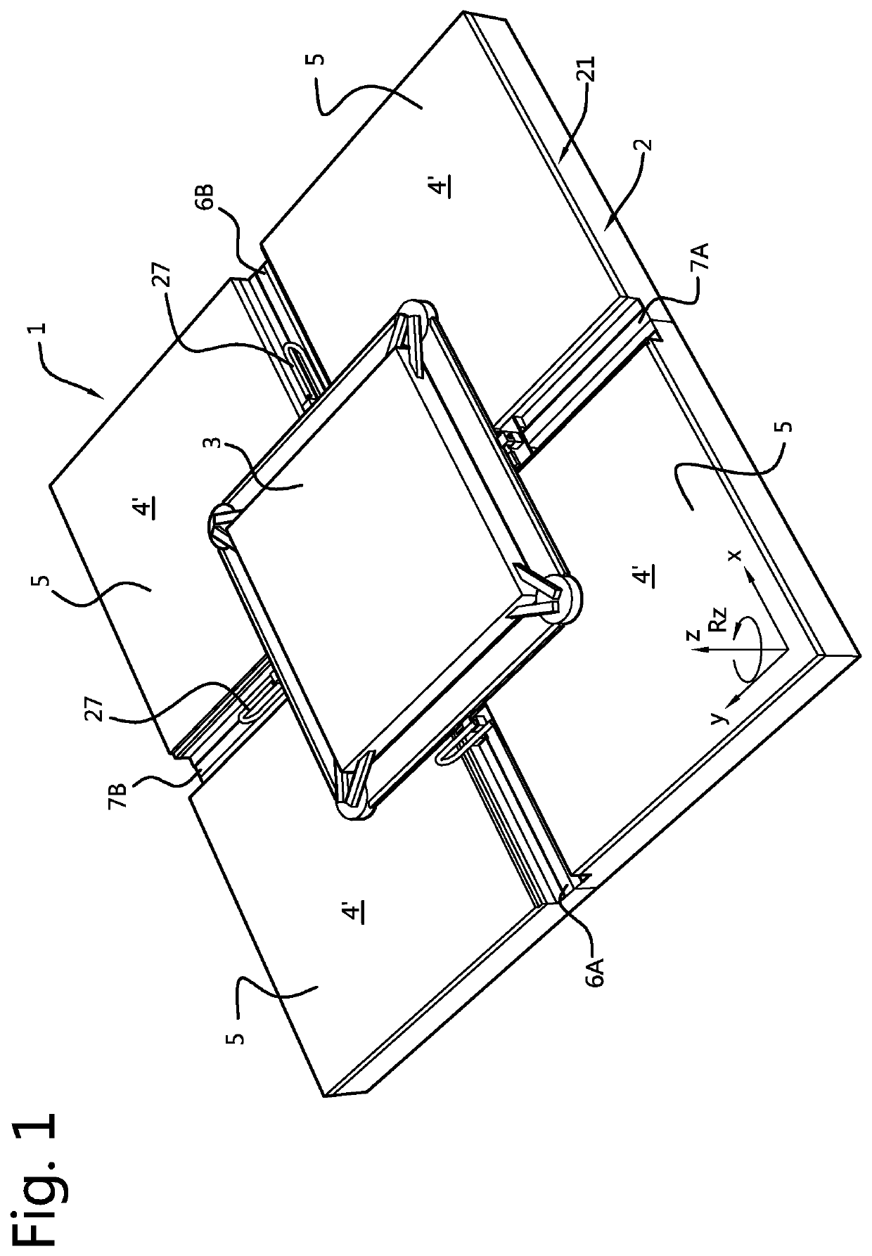
[0050]In FIG. 1 is shown a positioning device 1 which for example may be used to position substrates that have to be processed by a processing unit, e.g. in the semi-conductor industry.

[0051]The positioning device 1 comprises a base 2 and a movable stage 3 that is adapted to support and hold the substrate.

[0052]The base 2 comprises four flat bearing surface portions 4′. The four bearing surface portions 4′ are constituted by four stone slabs 5. The slabs 5 have a square shape and are positioned in a square configuration, whereby the base 2 in general has a square configuration. The upper surfaces 4′ of the four stone slabs 5 define together the flat bearing surface 4 of the base 2.

[0053]In a practical embodiment the stone slabs 5 are granite slabs, which are accurately processed to be provided with flat surfaces, straight edges and orthogonal sides.

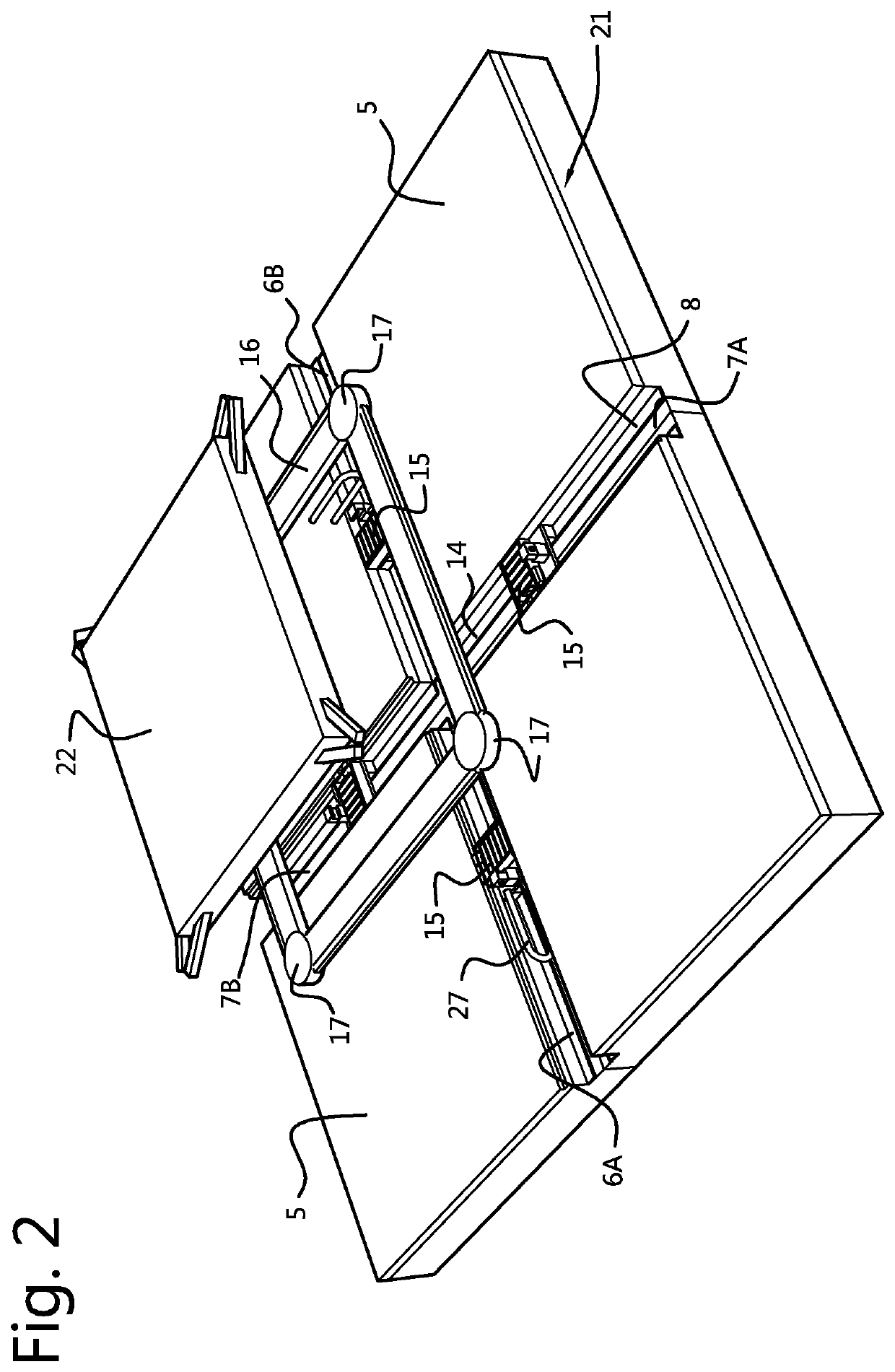
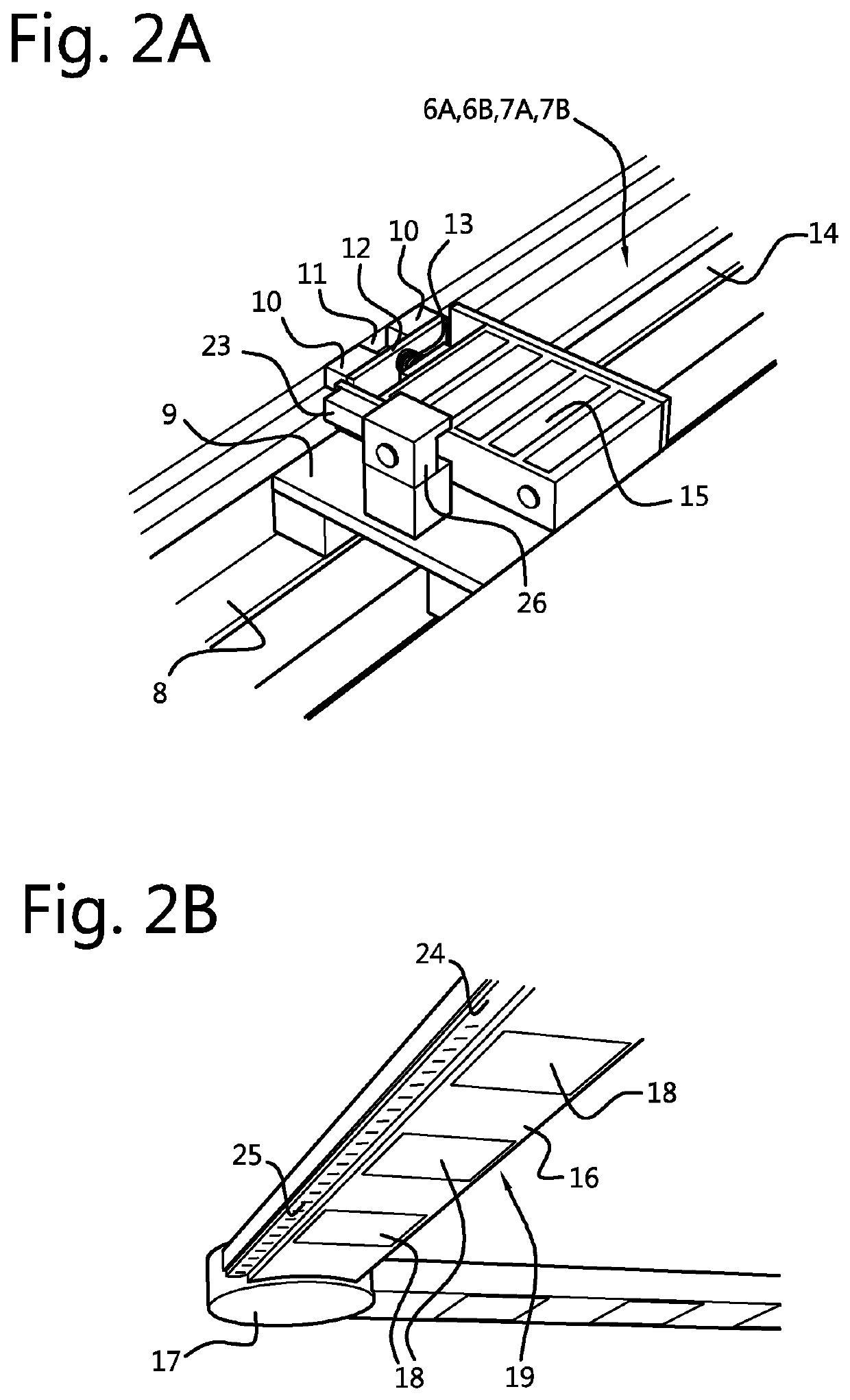
[0054]The slabs 5 are positioned on a mutual distance from each other, such that gaps 6A, 6B and 7A, 7B are provided between the slabs 5...


PUM


Abstract

A planar positioning device having three degrees of freedom (X, Y, Rz) includes a static base having a flat bearing surface and a moveable stage. The stage is moveable over the bearing surface in an XY-plane. The moveable stage includes air bearings and is supported without contact by the bearing surface via said air bearings. The device includes a linear motor acting in the X-direction and a linear motor acting in the Y-direction, and at least one additional linear motor acting in the X-direction or in the Y-direction. Each of the linear motors includes a magnet assembly arranged on the moveable stage and a coil assembly arranged on the base. The base includes a slider track extending in the X-direction and a slider track extending in the Y-direction. The sliders each have a reluctance actuator arranged on it to cooperate with (ferro)magnetic material on the moveable stage.

Description

CROSS-REFERENCE TO RELATED APPLICATIONS[0001]This application is the National Stage of International Application No. PCT / NL2018 / 050058, filed Jan. 29, 2018, which claims the benefit of Netherlands Application No. 2018266 (NL), filed Jan. 31, 2017, the contents of which is incorporated by reference herein.FIELD OF THE INVENTION[0002]The invention relates to a planar positioning device having three degrees of freedom (X, Y, Rz) comprising:[0003]a static base having a flat bearing surface; and[0004]a moveable stage, being moveable over the bearing surface of the base in an XY-plane parallel to the bearing surface by electromagnetic driving means, wherein the XY-plane is defined by orthogonal directions X and Y, and the moveable stage including air bearings and being supported without contact by the bearing surface of the base via said air bearings.BACKGROUND OF THE INVENTION[0005]A positioning device is known from DE 100 54 376. This known device has a base on which at least eight elon...

Claims


Application Information

Patent Timeline
IPC IPC(8): H02K41/03H02K11/21H01L21/68
CPCH02K41/031H02K2201/18H02K11/21H01L21/68H02K41/03
Inventor BELTMAN, AREND-JAN JOHAN
Owner CCM BEHEER BV NL
Why Eureka
Try Eureka