

Connector with electronic component
- Summary
- Abstract
- Description
- Claims
- Application Information
AI Technical Summary
Benefits of technology
Problems solved by technology
Method used
Image

Examples
Embodiment Construction
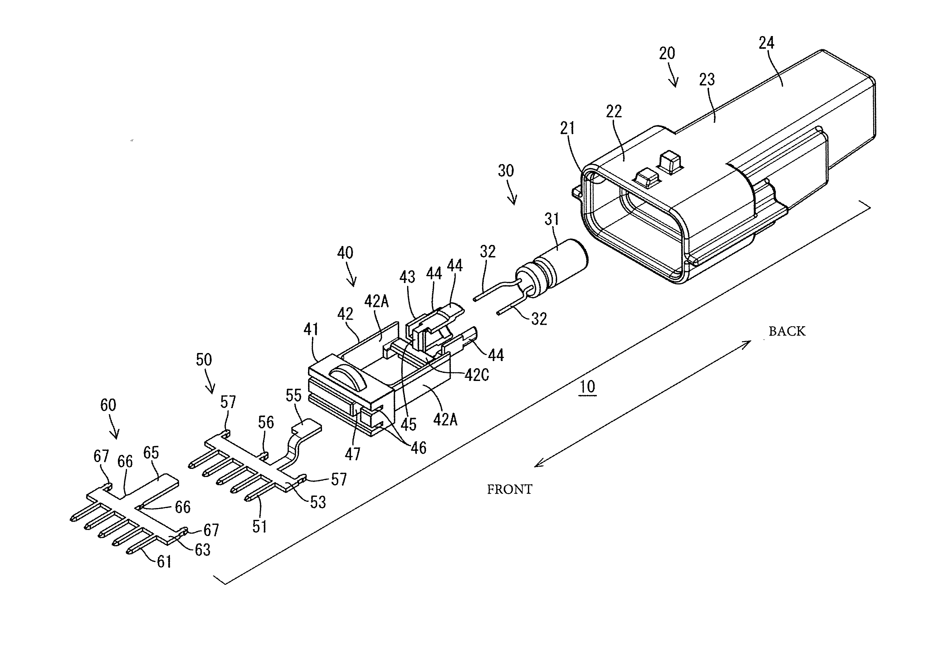
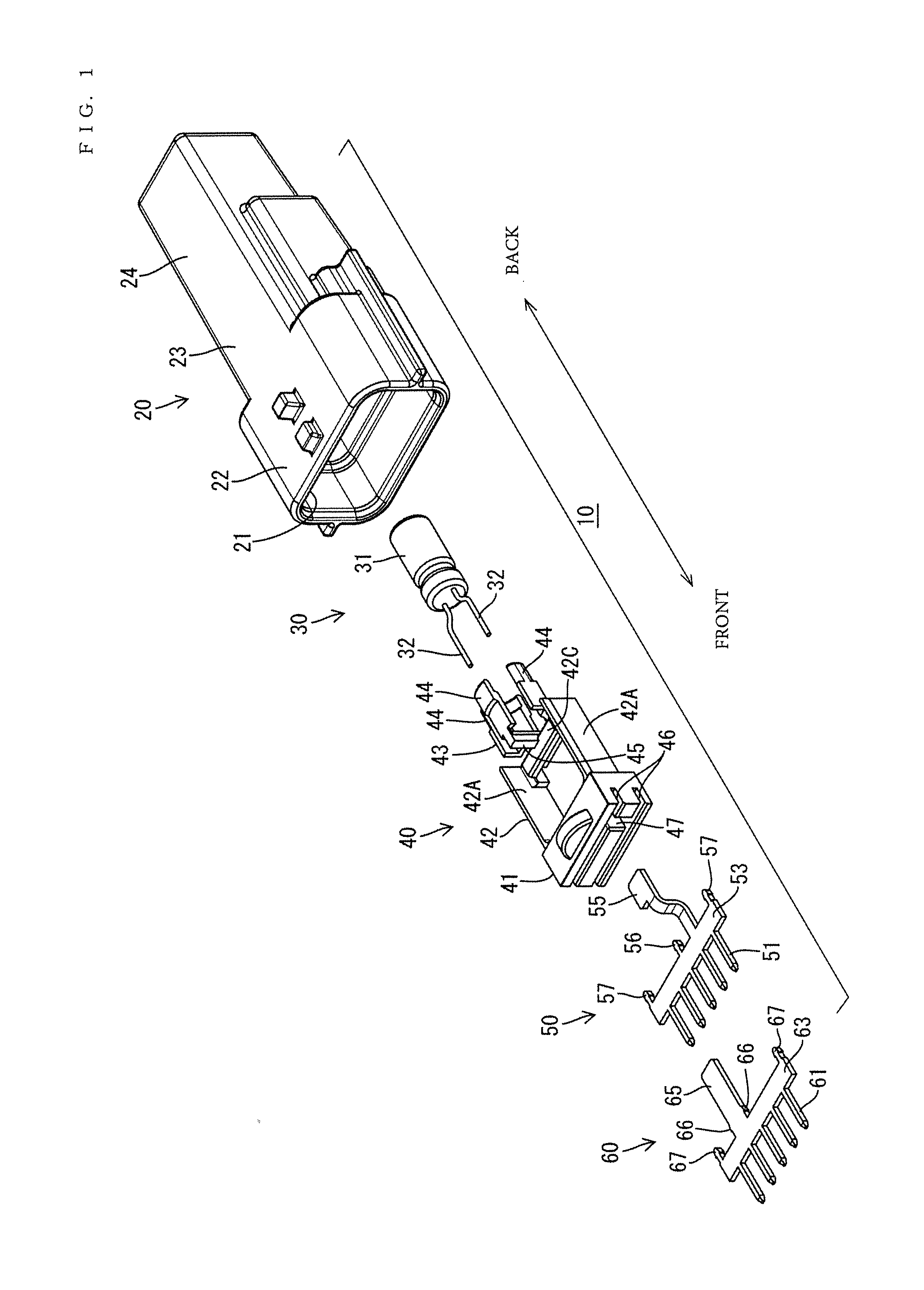
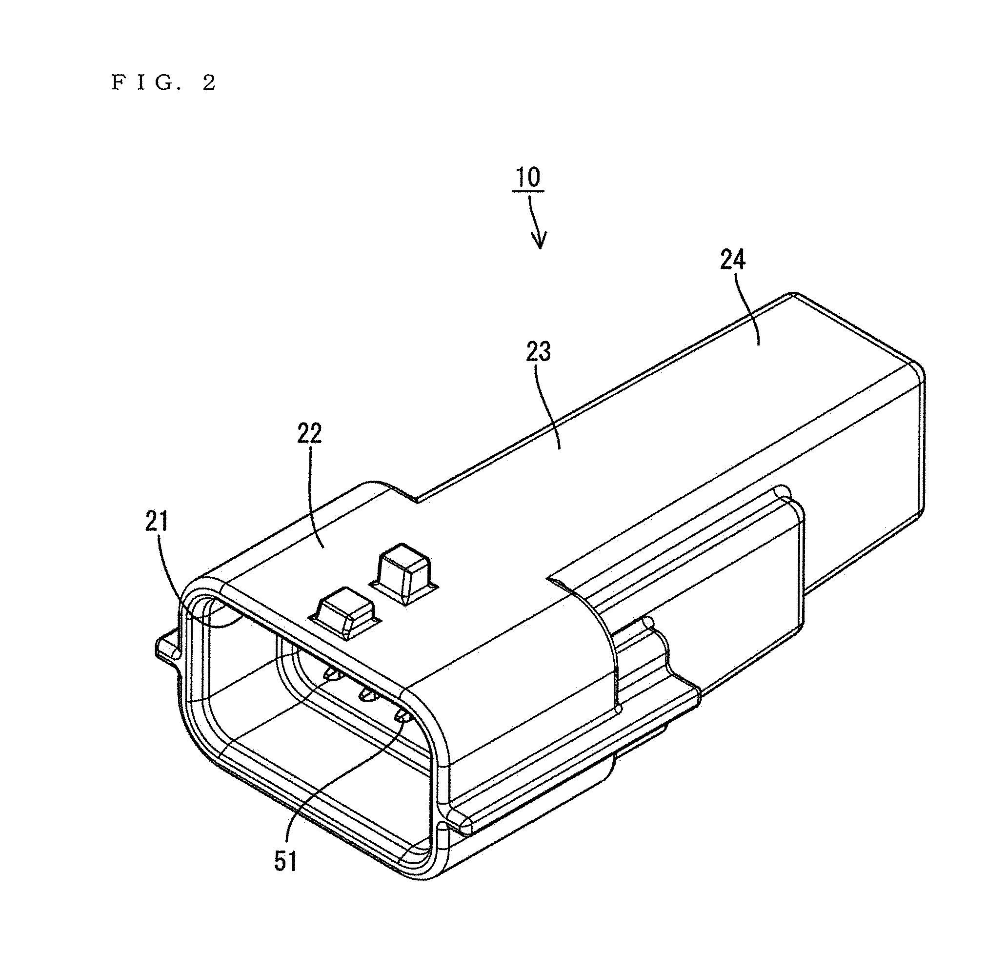
[0034]A connector in accordance with a first embodiment of the invention is illustrated in FIGS. 1 to 15 and is identified by the numeral 10. The connector 10 is a joint connector for collectively connecting unillustrated wires drawn out from electric / electronic devices installed in an automotive vehicle and has an electronic component for removing noise of the electric / electronic devices. As shown in FIG. 1, the connector 10 includes a bag-shaped housing main body 20 open only in one direction, a capacitor 30, a holder 40, a first busbar 50 and a second busbar 60. Further, the connector 10 is connectable to an unillustrated mating connector. Note that, in the following description, a front-back direction is based on arrow directions in FIG. 1, wherein an end to be connected to the mating connector is referred to as a front end.
[0035]The housing main body 20 is made unitarily of synthetic resin and includes an insertion opening 21 that opens to a receptacle 22 for receiving the mati...
PUM
 Abstract
Description
Claims
Application Information