Crimp terminal and terminal crimping device

Active Publication Date: 2017-06-22
YAZAKI CORP +1
View PDF7 Cites 9 Cited by
  • Summary
  • Abstract
  • Description
  • Claims
  • Application Information

AI Technical Summary

Benefits of technology

[0013]According to still another aspect of the present invention, a terminal crimping device includes a terminal supplying device configured to transfer a crimp terminal to a crimping position at which the crimp terminal is crimped to an electric wire; a crimping device configured to crimp the crimp terminal transferred to the crimping position to an end of the electric wire using a first die and a second die; and a driving device configured to reduce a gap between the first die and the second die during crimping process and increases the gap between the first die and the second die after the crimping process is completed, wherein the crimp terminal comprises a terminal fitting that includes a terminal connecting portion electrically connected to a counterpart terminal, an electric wire connecting portion electrically connected to the end of the electric wire placed on an inner wall surface side of the electric wire connecting portion by the crimping process, and a coupling portion that couples the terminal connecting portion and the electric wire connecting portion, the electric wire connecting portion being divided into a bottom on which the end of the electric wire is placed during the crimping process, a first barrel piece extending from one end of the bottom, wound around the end of the electric wire, and positioned on an inner side, and a second barrel piece extending from the other end of the bottom longer than the first barrel piece, wound around the end of the electric wire and the first barrel piece, and positioned on an outer side, and a water stop member that is affixed to the inner wall surface of the electric wire connecting portion before the crimping process is performed and config

Problems solved by technology

In these caulking structures, the end surfaces of the respective barrel pieces may possibly come into contact with each other in the caulking process, resulting in deformation of the barrel pieces, displacement

Method used


Image

  • Crimp terminal and terminal crimping device
  • Crimp terminal and terminal crimping device
  • Crimp terminal and terminal crimping device

Examples


embodiments

[0048]An embodiment of the crimp terminal and the terminal crimping device according to the present invention is described with reference to FIGS. 1 to 30.

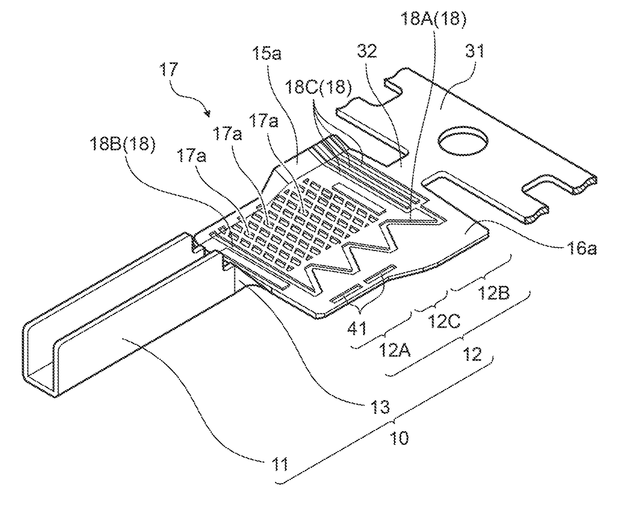
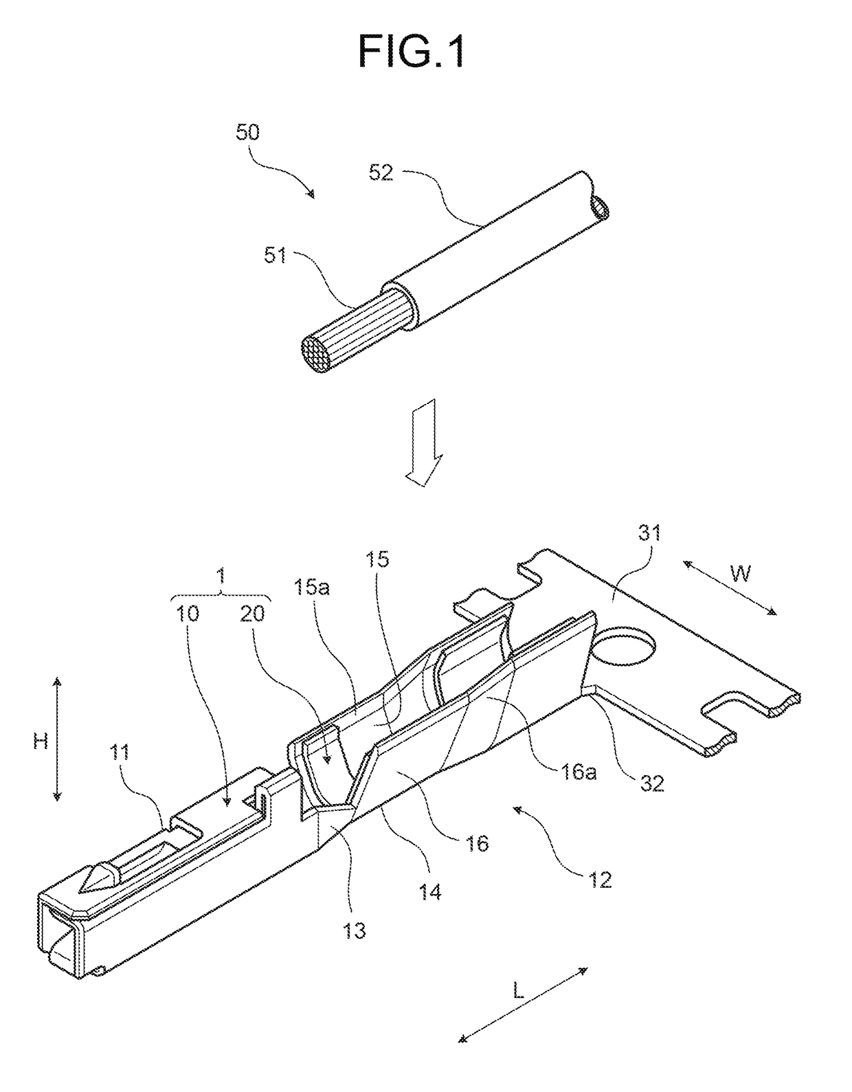
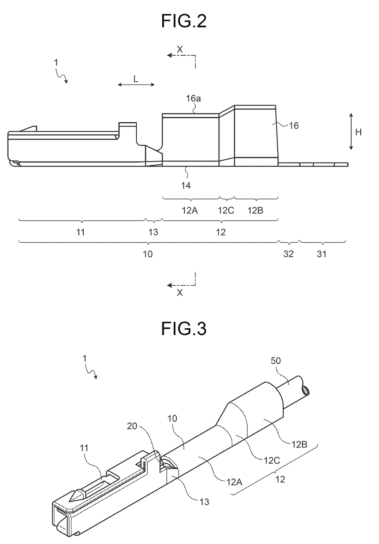
[0049]The crimp terminal according to the present embodiment is represented by reference numeral 1 in FIGS. 1 to 4. The crimp terminal 1 is electrically connected to an electric wire 50 and electrically connected to a counterpart terminal (not illustrated) while being integrated with the electric wire 50. At an end of the electric wire 50, a cover 52 is removed by a predetermined length so as to expose a core wire 51 by the predetermined length. The core wire 51 may be an aggregate of a plurality of wires or a solid wire, such as a coaxial cable. To electrically connect the crimp terminal 1 to the electric wire 50, the crimp terminal 1 is crimped to the end of the electric wire 50. As a result, the crimp terminal 1 is electrically connected to the core wire 51 at the exposed distal end (hereinafter, simply referred to as a “core w...


PUM


Abstract

A terminal fitting includes a terminal connecting portion and an electric wire connecting portion. A water stop member is affixed to an inner wall surface of the electric wire connecting portion before crimping process and suppresses entering of water between the electric wire connecting portion and a core wire of the electric wire after the crimping. The electric wire connecting portion is formed into a U-shape by raising the first barrel piece and the second barrel piece from both ends of the bottom. The distal end of the first barrel piece is bent toward the second barrel piece, to form a gap between a slide contact surface on a descending second die and the distal end of the first barrel piece.

Description

CROSS-REFERENCE TO RELATED APPLICATION(S)[0001]The present application claims priority to and incorporates by reference the entire contents of Japanese Patent Application No. 2015-244872 filed in Japan on Dec. 16, 2015.BACKGROUND OF THE INVENTION[0002]1. Field of the Invention[0003]The present invention relates to a crimp terminal and a terminal crimping device.[0004]2. Description of the Related Art[0005]Conventionally known are crimp terminals including an electric wire connecting portion electrically connected to a core wire of an electric wire. Such a crimp terminal and an electric wire are crimped by a terminal crimping device, thereby being electrically connected to each other. Crimp terminals and terminal crimping devices of this kind need to prevent entering of water between the electric wire connecting portion and the core wire of the electric wire. Japanese Patent Application Laid-open No. 2014-182957 and Japanese Patent Application Laid-open No. 2014-182958, for example, ...

Claims


Application Information

Patent Timeline
IPC IPC(8): H01R4/18H01R43/055
CPCH01R43/055H01R4/185H01R4/18H01R43/0482H01R43/05H01R4/188H01R13/52
Inventor SHINOHARA, JUNYAIWATA, MASASHIOHTAKA, KAZUTOKOBAYASHITAGA, HIROYASUHARA, MOTOYANAKATA, HIROHITOTAKAHASHI, KAZUHIDEYOSHIDA, TAKATO
Owner YAZAKI CORP
Why Eureka
Try Eureka