Crimp terminal

a technology of crimping terminals and connectors, which is applied in the direction of coupling contact members, coupling device connections, connection insulation, etc., can solve the problems of deteriorating the water stop performance of the electric wire connecting portion, and achieve the effect of high water stop performan

Active Publication Date: 2017-06-22
YAZAKI CORP +1
View PDF7 Cites 9 Cited by
  • Summary
  • Abstract
  • Description
  • Claims
  • Application Information

AI Technical Summary

Benefits of technology

[0007]The present invention aims to provide a crimp terminal having high water stop performance in an electric wire connecting portion.

Problems solved by technology

In the conventional crimp terminals, part of the water stop sheet or the insulating resin layer on the second barrel piece may possibly be scraped off in the caulking process, thereby deteriorating the water stop performance in the electric wire connecting portion.

Method used


Image

  • Crimp terminal
  • Crimp terminal
  • Crimp terminal

Examples


embodiments

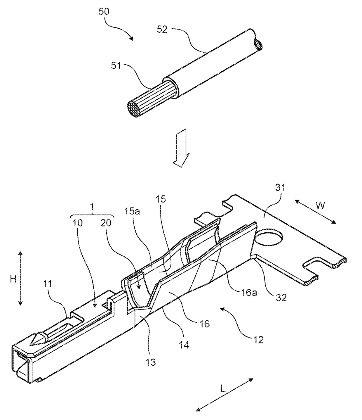
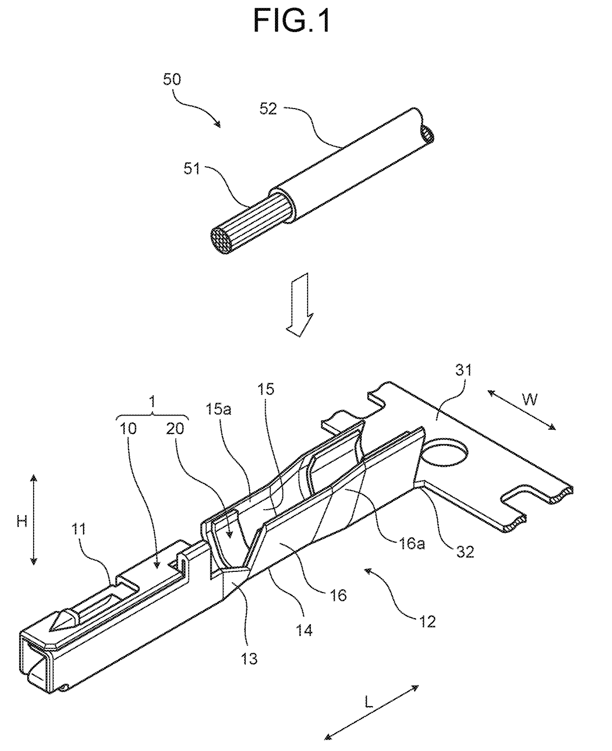
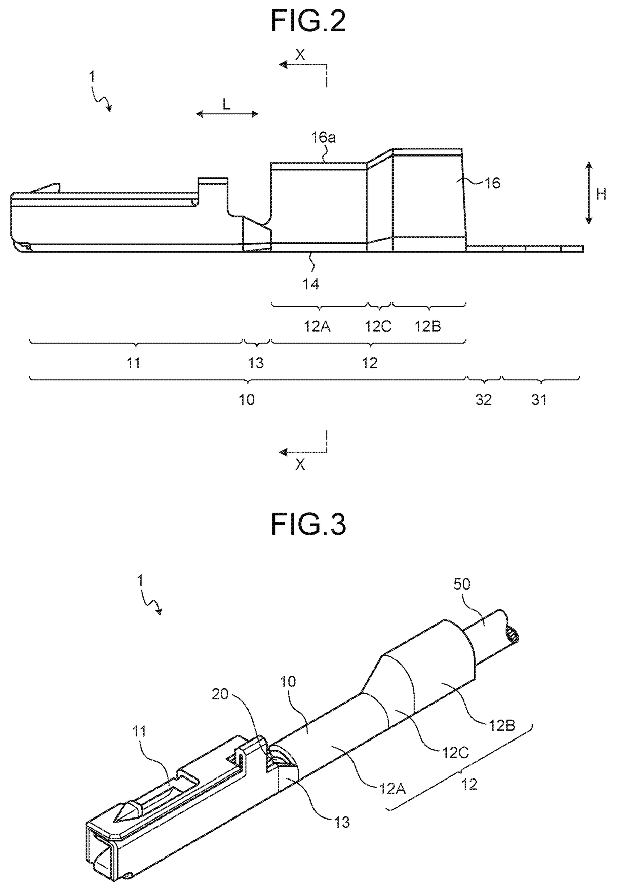
[0045]An embodiment of the crimp terminal according to the present invention is described with reference to FIGS. 1 to 30.

[0046]The crimp terminal according to the present embodiment is represented by reference numeral 1 in FIGS. 1 to 4. The crimp terminal 1 is electrically connected to an electric wire 50 and electrically connected to a counterpart terminal (not illustrated) while being integrated with the electric wire 50. At an end of the electric wire 50, a cover 52 is removed by a predetermined length so as to expose a core wire 51 by the predetermined length. The core wire 51 may be an aggregate of a plurality of wires or a solid wire, such as a coaxial cable. To electrically connect the crimp terminal 1 to the electric wire 50, the crimp terminal 1 is crimped to the end of the electric wire 50. As a result, the crimp terminal 1 is electrically connected to the core wire 51 at the exposed distal end (hereinafter, simply referred to as a “core wire at the distal end”).

[0047]Spe...


PUM


Abstract

A water stop member of a crimp terminal is affixed to the inner wall surface of an electric wire connecting portion of a terminal fitting before crimping and forms into a first water stop area, a second water stop area, and a third water stop area after the crimping. The first water stop area suppresses entering of water from a space between the outer wall surface of a first barrel piece and the inner wall surface of a second barrel piece in the electric wire connecting portion. The second water stop area suppresses entering of water from the side closer to a terminal connecting portion of the terminal fitting than the distal end position of a core wire. The third water stop area suppresses entering of water from a space between the inner wall surface of a cover crimping portion of the electric wire connecting portion and a cover.

Description

CROSS-REFERENCE TO RELATED APPLICATION(S)[0001]The present application claims priority to and incorporates by reference the entire contents of Japanese Patent Application No. 2015-244869 filed in Japan on Dec. 16, 2015.BACKGROUND OF THE INVENTION[0002]1. Field of the Invention[0003]The present invention relates to a crimp terminal.[0004]2. Description of the Related Art[0005]Conventionally known are crimp terminals including an electric wire connecting portion electrically connected to a core wire of an electric wire. Such a crimp terminal is crimped by a terminal crimping device, thereby being electrically connected to each other. Crimp terminals and terminal crimping devices of this kind need to prevent entering of water between the electric wire connecting portion and the core wire of the electric wire. Japanese Patent Application Laid-open No. 2014-182957 and Japanese Patent Application Laid-open No. 2014-182958, for example, include a water stop part that blocks a gap between a...

Claims


Application Information

Patent Timeline
Patent Type & Authority Applications(United States)
IPC IPC(8): H01R4/18H01R13/11
CPCH01R13/114H01R4/185H01R4/184H01R4/188H01R4/70H01R43/048H01R43/055H01R13/5216
Inventor YOSHIDA, TAKATOFUKUDA, MASARUKOBAYASHI, HIROSHITAGA, HIROYASUHARA, MOTOYAOSADA, TAKESHI
Owner YAZAKI CORP
Why Eureka
Try Eureka