Pipe jacking tunnel inlet stop water device

A technology for water-stopping and tunneling at the entrance, which is applied in tunnels, tunnel linings, shaft equipment, etc., can solve the problems of unsatisfactory water-stopping effect, limited use and failure, etc. The effect of improving the service life

Inactive Publication Date: 2017-05-24
SOUTH CHINA UNIV OF TECH
View PDF9 Cites 6 Cited by
  • Summary
  • Abstract
  • Description
  • Claims
  • Application Information

AI Technical Summary

Problems solved by technology

At present, rubber curtains are usually used to stop the water at the pipe jacking hole. The water-stopping effect of this method is not ideal, and it often fails due to wear and tear during the long-distance jacking process, and it is generally only used in normal-pressure soil layers. Happening

Method used


Image

  • Pipe jacking tunnel inlet stop water device
  • Pipe jacking tunnel inlet stop water device
  • Pipe jacking tunnel inlet stop water device

Examples


Embodiment 1

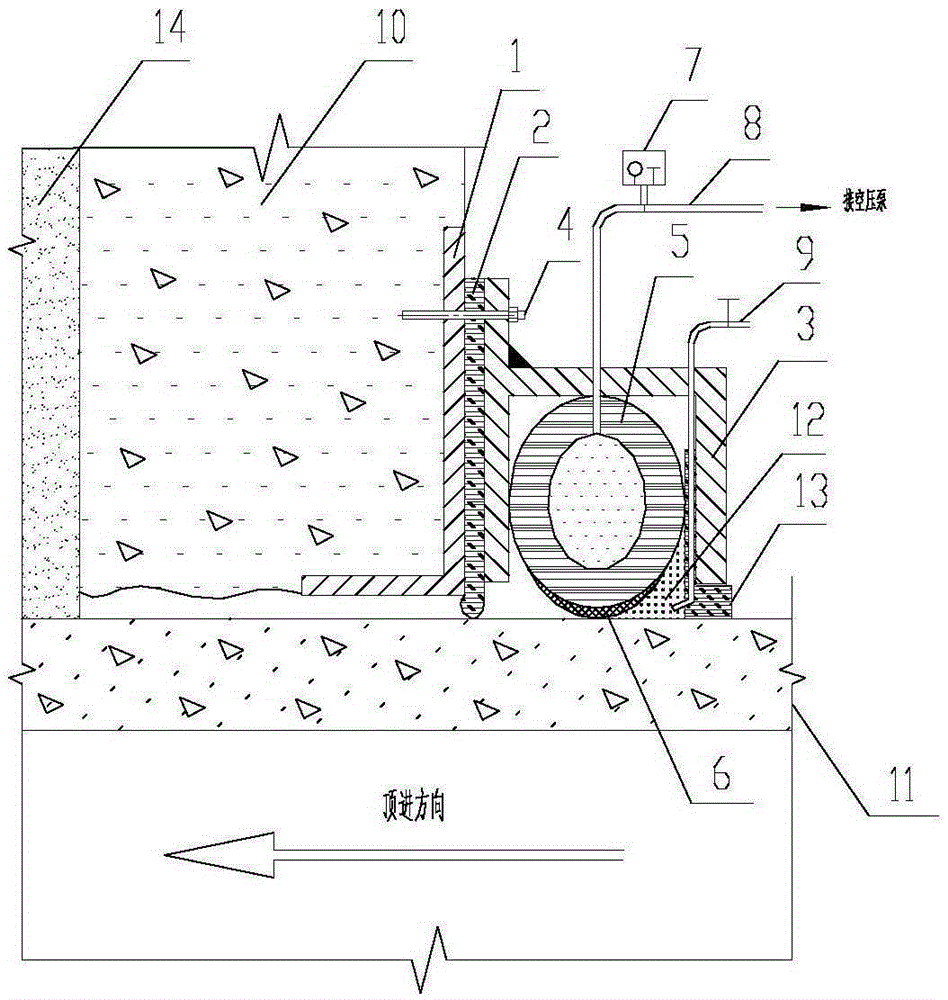
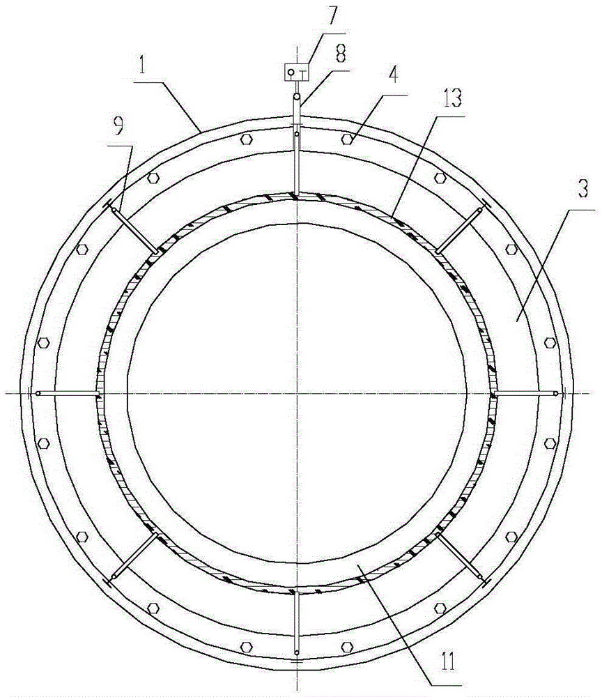
[0028] as attached figure 1 And attached figure 2 As shown, a water stop device at the entrance of a pipe jacking tunnel includes an inflatable rubber water stop ring installation groove 3 fixedly arranged on the shaft wall 10 of the pipe jacking tunnel entrance, and an installation groove 3 of the inflatable rubber water stop ring The flexible inflatable rubber water-stop ring 5 inside, the air guide tube 8 connecting the inflatable rubber water-stop ring 5 and the ground air compressor is also arranged on the installation groove 3 of the inflatable rubber water-stop ring, and the pipe joint 11 of this embodiment The cross-section is circular, the outer diameter is 2980mm, and the hole diameter is 3020mm. The shape of the inflatable rubber water-stop ring installation groove 3 and the inflatable rubber water-stop ring 5 matches the cross-sectional shape of the pipe joint 11, which is circular .

[0029] The hole is equipped with a pre-embedded installation flange 1, a curt...

Embodiment 2

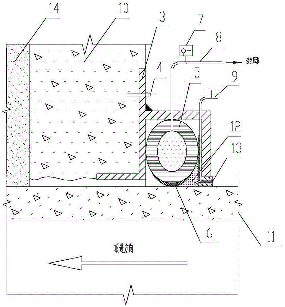
[0040] as attached image 3 And attached Figure 4 As shown, a water stop device at the entrance of a pipe jacking tunnel includes an inflatable rubber water stop ring installation groove 3 fixedly arranged on the shaft wall 10 of the pipe jacking tunnel entrance, and an installation groove 3 of the inflatable rubber water stop ring The flexible inflatable rubber water-stop ring 5 inside, the air guide tube 8 connecting the inflatable rubber water-stop ring 5 and the ground air compressor is also arranged on the installation groove 3 of the inflatable rubber water-stop ring, and the pipe joint 11 of this embodiment The cross section is rectangular, the height × width of the outer circumference of the pipe joint is 3500 mm × 3000 mm, and the wall thickness is 250 mm; the shape of the installation groove 3 of the inflatable rubber water stop ring and the shape of the inflatable rubber water stop ring 5 matches the shape of the cross section of the pipe joint 11 , in a rectangul...


PUM


Abstract

The invention relates to a pipe jacking tunnel inlet stop water device, which comprises an inflatable rubber sealing ring installation slot fixed on a borehole of a pipe jacking tunnel, and an inflatable flexible rubber sealing ring installed in the inflatable rubber seal a flexible rubber seal ring mounting groove. The inflatable rubber sealing ring installation slot is further provided with an air pipe connecting the inflatable rubber sealing ring and a ground air pump. In an inflated state, an outer side of the inflatable rubber sealing ring is in close contact with the bottom of a hole fitting groove, and an inner side faces an outer surface of a pipe joint. At the same time, the inflatable rubber sealing ring of the air pipe connects with an automatic pressure keeping and warning device. The water makes the rubber ring maintain the pressure in a normal working pressure range. While there is inflatable ring grinding off the gas and other abnormal phenomena, the device will automatically alarm. The pipe jacking tunnel inlet stop water device has the advantages of good sealing reliability and wear resistance and is applicable to the hole sealing of round and rectangular and other special-shaped cross-section of the tunnel construction.

Description

technical field [0001] The invention relates to a water stop device at the inlet of a pipe jacking tunnel, and the method can be applied to the fields of electric power engineering, municipal engineering, water conservancy engineering, traffic engineering and the like. Background technique [0002] As a trenchless construction method, the pipe jacking method is widely used in the development and construction of urban underground space due to its outstanding advantages such as little impact on urban traffic and environmental safety, advanced technology, high efficiency, and low construction cost. In the pipe jacking project, in order to make the pipe energy-saving and smooth jacking, a hole is reserved on the working shaft wall. The hole is slightly larger than the outer diameter of the pipe joint. There is a certain gap between the hole circumference and the outer surface of the pipe joint. At the same time, it is necessary to reinforce the soil within a certain range of the...

Claims


Application Information

Patent Timeline
Patent Type & Authority Applications(China)
IPC IPC(8): E21D11/38
Inventor 房营光欧振锋谷任国李波
Owner SOUTH CHINA UNIV OF TECH
Why Eureka
Try Eureka