Check patentability & draft patents in minutes with Patsnap Eureka AI!

Method of encoding raw color coordinates provided by a camera representing colors of a scene having two different illuminations

Inactive Publication Date: 2017-06-22
THOMSON LICENSING SA
View PDF0 Cites 3 Cited by
  • Summary
  • Abstract
  • Description
  • Claims
  • Application Information

AI Technical Summary

Benefits of technology

The patent describes a method for encoding colors in a way that takes into account the high and low luminance levels of different illumination sources in a scene. This method uses a linear model to capture the color coordinates of the scene and assign weights to each color based on its luminance. The encoded colors can then be decoded using the same linear model to accurately represent the colors in a device-independent color space. The technical effect of this method is to capture and encode the colors of a scene in a way that is sensitive to the different levels of illumination, resulting in a more accurate representation of the colors in a device-independent color space.

Problems solved by technology

However, this solution has the disadvantage that, after selection, the classical well-known white balancing based on a single white is applied.
The result is not adapted to multiple whites for the same part of an image, for instance for a same pixel.
It is known that reproduction of a large range of colors such as highly saturated colors or colors with high dynamic range is difficult on color display devices that are available today on the market.

Method used


Image

  • Method of encoding raw color coordinates provided by a camera representing colors of a scene having two different illuminations
  • Method of encoding raw color coordinates provided by a camera representing colors of a scene having two different illuminations
  • Method of encoding raw color coordinates provided by a camera representing colors of a scene having two different illuminations

Examples


first embodiment

of Decoding Method

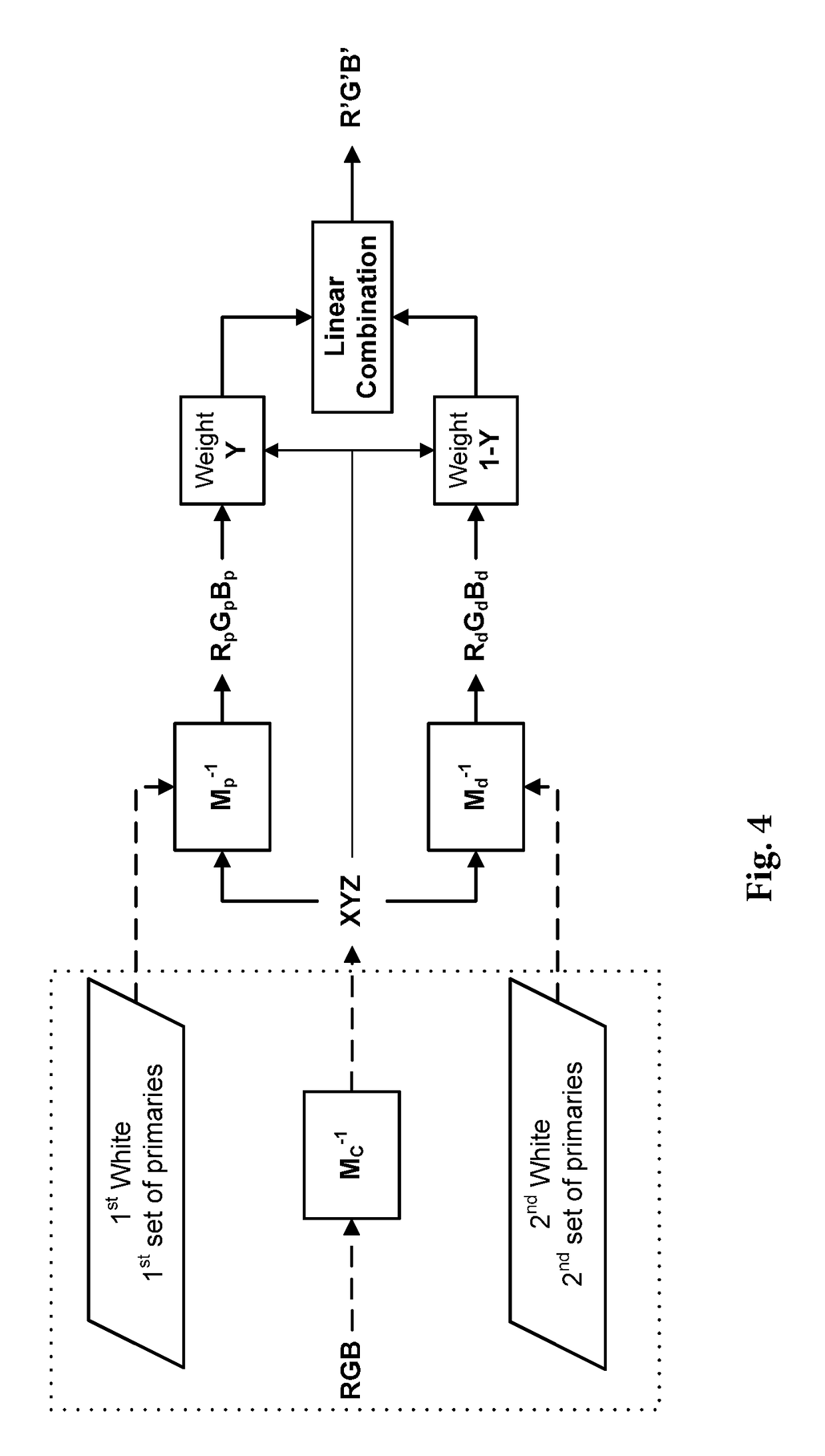
[0099]In a first step of this first embodiment, it is assumed that this illumination is diffuse and that peak illumination can be neglected. Therefore, the matrix Md modeling the second virtual display device (i.e. corresponding to the diffuse white) is applied to each set of encoded colors coordinates R′,G′,B′ representing a color, as if this color should be displayed by this second virtual display device. A first set of corresponding color coordinates X1′,Y1′,Z1′ representing the same color in the CIE-XYZ color space are then obtained:

[X1″Y1″Z1″]=Md[R′G′B′]

[0100]In a second step of this first embodiment, it is considered that the color coordinates R′,G′,B′ have been encoded as described above, i.e. that they have been computed by linearly combining a set of device-dependent color coordinates based on the first virtual display device with a first weight w and a set of device-dependent color coordinates based on the second virtual display device with a second weigh...

second embodiment

of Decoding Method

[0105]The first step of this second embodiment is the same as the first step of this first embodiment above.

[0106]The second step comprises a series of iterations as described below.

[0107]In a first iteration of this second step, the same equation as in the second step of the first embodiment above is used to compute a second set of decoded color coordinates X3″,Y3″,Z3″:

(R′G′B′)=w″Mp-1(X3″Y3″Z3″)+(1-w″)Md-1(X3″Y3″Z3″)

[0108]Then, it is assumed that w″=Y3″. The above equation then becomes:

(R′G′B′)=Y3″Mp-1(X3″Y3″Z3″)+(1-Y3″)Md-1(X3″Y3″Z3″)=Md-1(X3″Y3″Z3″)+(Mp-1-Md-1)(X3″Y3″Y3″Y3″Z3″Y3″)

[0109]This equation cannot be resolved in closed form for the second decoded color coordinates. Therefore, this equation is reformulated as follows to compute a first set of decoded color coordinates X3″,Y3″,Z3″:

(X3″Y3″Z3″)=Md(R′G′B′)+(1-MdMp-1)(X0Y0Y0Y0Z0Y0)with(X0Y0Z0)=(X1″Y1″Z1″),whereX1″,Y1″,Z1″

are provided by the first step.

[0110]A second iteration is then implemented using the sam...


PUM


Abstract

This method is based on a linear combination of a first encoding of each color based on a first virtual display device notably defined by a first white and a first set of primaries corresponding to colors reflected from the scene under the illumination with the highest luminance, and of a second encoding based on a second virtual display device notably defined by a second white and a second set of primaries corresponding to colors reflected from the scene under the illumination with the lowest luminance, wherein the weight assigned to the first encoding is proportional to the luminance of said color.

Description

REFERENCE TO RELATED EUROPEAN APPLICATION[0001]This application claims priority from European Application No. 15307040.4, entitled “Method Of Encoding Raw Color Coordinates Provided By A Camera Representing Colors Of A Scene Having Two Different Illuminations,” filed on Dec. 17, 2015, the contents of which are hereby incorporated by reference in its entirety.TECHNICAL FIELD[0002]The invention relates to the encoding of colors of images having at least two different whites, one of those being related to a far brighter part of the image. The invention addresses notably images having a peak-white and a diffuse-white, wherein the part of the image illuminated by the peak-white is far brighter that the part of the image illuminated by the diffuse-white. Such images are notably high dynamic range images.BACKGROUND ART[0003]As shown on FIG. 1, a camera transforms the spectral light stimulus of each color of a scene captured by this camera into raw color coordinates representing this color ...

Claims


Application Information

Patent Timeline
IPC IPC(8): H04N9/73H04N1/60H04N19/179G06T7/90G06T9/00H04N19/186
CPCH04N9/735G06T9/00H04N19/186G06T2207/10024G06T7/90H04N1/6086H04N1/6077H04N19/179H04N9/67H04N19/46H04N19/85H04N23/88
Inventor STAUDER, JURGENREINHARD, ERIKMORVAN, PATRICK
Owner THOMSON LICENSING SA
Features
  • R&D
  • Intellectual Property
  • Life Sciences
  • Materials
  • Tech Scout
  • Unparalleled Data Quality
  • Higher Quality Content
  • 60% Fewer Hallucinations
Learn More