Image forming apparatus and method for controlling the same
- Summary
- Abstract
- Description
- Claims
- Application Information
AI Technical Summary
Benefits of technology
Problems solved by technology
Method used
Image
Examples
first embodiment
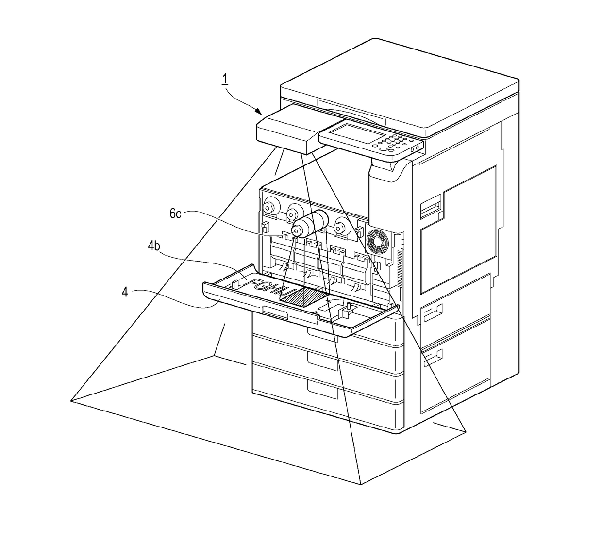
[0048]In this embodiment, work to replace a toner bottle 6c in which the toner level becomes zero or less than a predetermined threshold into a low toner level state will be described as an example of the user maintenance work (user work). The low toner level corresponds to an event that needs maintenance work.
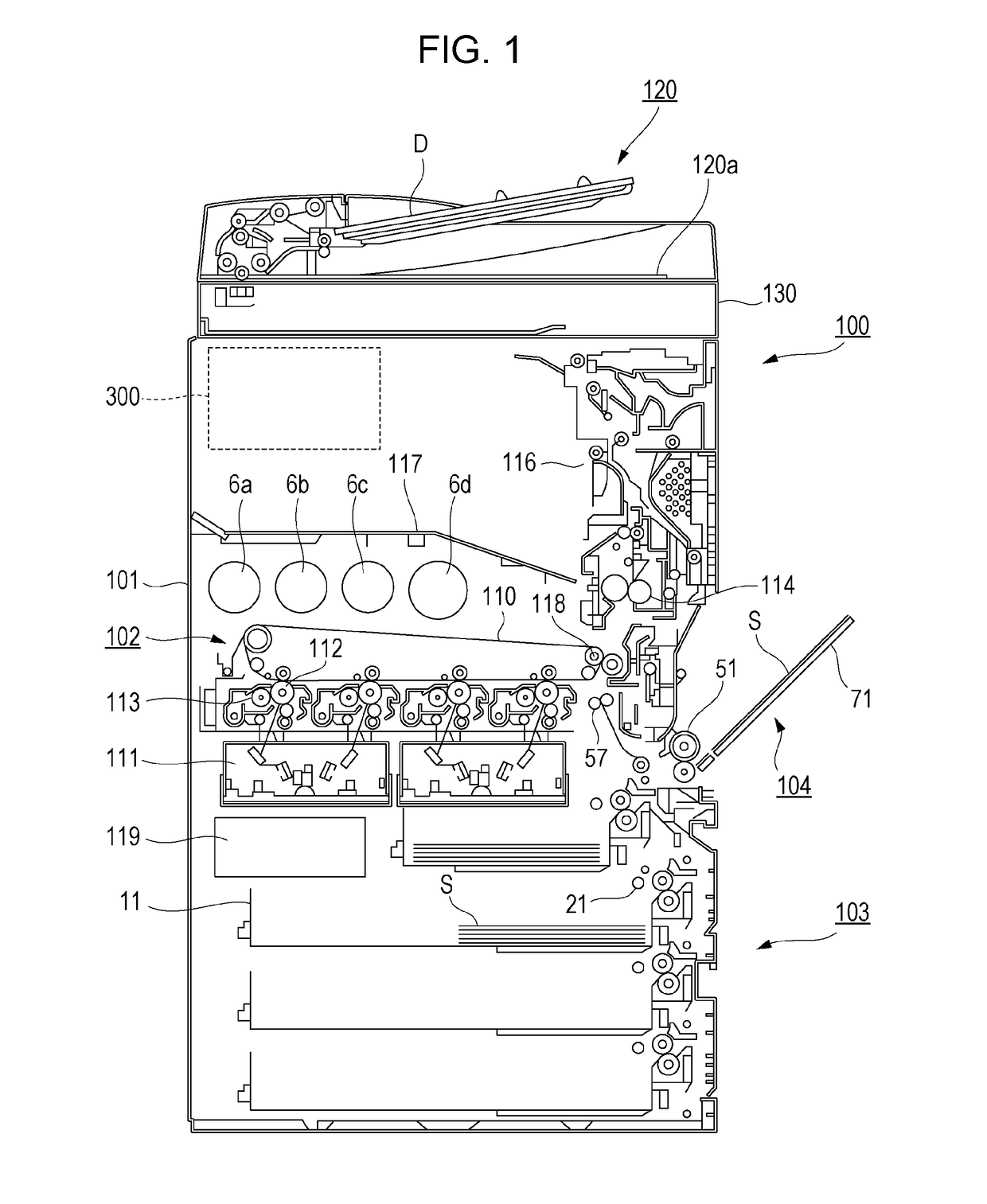
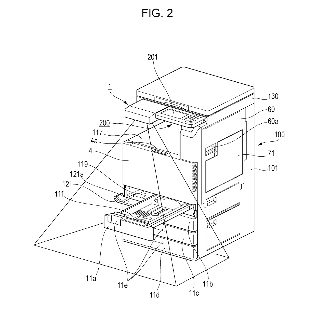
[0049]FIG. 1 is a diagram illustrating the configuration of an image forming apparatus 100. An image scanning unit 130 is provided on the top of a printer main body 101. The image scanning unit 130 scans a document D placed on a platen glass 120a serving as a document table by an automatic document feeding unit 120. An image forming unit 102, a sheet feeding unit 103 and a manual feeding unit 104 that feed sheets (printing media) S to the image forming unit 102 are provided below the image scanning unit 130. The image forming unit 102 includes laser scanner units 111, photosensitive drums 112, developing units 113, and toner bottles 6a, 6b, 6c, and 6d. The sheet feeding unit 1...
second embodiment
[0072]In this embodiment, the work of replacing the waste-toner container 119 in which a predetermined amount or more of waste toner accumulates will be described as an example of the user maintenance work (user work).
[0073]FIG. 11 is a block diagram illustrating the relationship among the control unit 300, detecting units, and an output unit of this embodiment. As illustrated in FIG. 11, the operating unit 200 and the projector unit 1 are connected to the control unit 300. The waste-toner-container fill-up detecting unit 33, the waste-toner-container presence detecting unit 34, and the waste-toner-container-door open / close detecting unit 35 are connected to the control unit 300. The control unit 300 controls information to be displayed with the operating unit 200 and the projector unit 1 based on signals from the detecting units 33 to 35.
[0074]FIGS. 12A and 12B are flowcharts for a display control process when the waste-toner container 119 is to be replaced. First, the CPU 601 moni...
third embodiment
[0080]In this embodiment, a sheet supply operation when the sheets S in the sheet container 11b run out will be described as an example of the user maintenance work (user work).
[0081]FIG. 16 is a block diagram illustrating the relationship among the control unit 300, detecting units, and an output unit of this embodiment. As illustrated in FIG. 16, the operating unit 200 and the projector unit 1 are connected to the control unit 300. The sheet-container sheet-presence detecting units 37a, 37b, 37c, and 37d and the sheet-container sheet-size detecting units 38a, 38b, 38c, and 38d are connected to the control unit 300. The sheet-container open / close detecting unit 39a, 39b, 39c, and 39d and the sheet-container position detecting units 40a, 40b, 40c, and 40d are also connected to the control unit 300. The control unit 300 controls information to be displayed with the operating unit 200 and the projector unit 1 based on information from the individual detecting units.
[0082]FIGS. 17A and...
PUM
 Abstract
Description
Claims
Application Information
 - R&D
- Intellectual Property
- Life Sciences
- Materials
- Tech Scout
- Unparalleled Data Quality
- Higher Quality Content
- 60% Fewer Hallucinations
Browse by: Latest US Patents, China's latest patents, Technical Efficacy Thesaurus, Application Domain, Technology Topic, Popular Technical Reports.
© 2025 PatSnap. All rights reserved.Legal|Privacy policy|Modern Slavery Act Transparency Statement|Sitemap|About US| Contact US: help@patsnap.com


