Modular antennas in wireless power transmission systems

a technology of wireless power transmission system and module antenna, which is applied in the direction of circuit arrangement, electrical equipment, de-icing/drying out arrangement, etc., can solve the problems of unaccounted for or unwanted interference among power waves, and achieve the effects of reducing potential, expanding the capabilities of the transmitter and the transmitter board, and reducing the potential

Active Publication Date: 2017-06-29
ENERGOUS CORPORATION
View PDF5 Cites 67 Cited by
  • Summary
  • Abstract
  • Description
  • Claims
  • Application Information

AI Technical Summary

Benefits of technology

[0007]Wireless power transmission systems disclosed herein attempt to address the above issues and may provide a number of other benefits as well. Wireless power transmission system described herein provide transmitter antennas that can be integrated into a printed circuit board, and thereby solves the above mentioned drawbacks of the sufficiently large dimensioned antennas being employed in the conventional wireless power transmission system. The transmitters may comprise expandable transmitter boards that comprise ports configured to receive new antenna boards, thereby allowing end-users to expand the capabilities of the transmitter and transmitter board by adding additional antenna boards. The transmitter board may comprise specially-programmed integrated circuits, such as a processor and / or a timing circuit, that not only control and manage generation and transmission of power waves, but may also manage the transmitter's configurations to dynamically account for new antenna boards. Such dynamic reconfigurations of how the integrated circuits and the antennas of the transmitter function may prevent, or at least mitigate, the potential for the power waves to interact in an undesired manner, due to the expansion due to addition of the new antenna board. Otherwise, when a new antenna board is added, the behavior of the transmitter and the antennas might cause unaccounted for or unwanted interference among the power waves. As an example, a processor may be configured to automatically detect a new antenna board connected to an empty port of the transmitter board, and then automatically re-configure various operational parameters and behaviors, such as the selection parameters for activating certain antenna boards during power wave transmission. As another example, the processor may re-configure waveform generation parameters that are used to determine the waveform characteristics of the power waves during power wave generation and transmission.

Problems solved by technology

Otherwise, when a new antenna board is added, the behavior of the transmitter and the antennas might cause unaccounted for or unwanted interference among the power waves.

Method used


Image

  • Modular antennas in wireless power transmission systems
  • Modular antennas in wireless power transmission systems
  • Modular antennas in wireless power transmission systems

Examples


Embodiment Construction

[0029]Reference will now be made to the exemplary embodiments illustrated in the drawings, where specific language will be used here to describe the same. It should be understood that no limitation of the scope of the invention is intended by the descriptions of such exemplary embodiments. Alterations and further modifications of the exemplary embodiments and additional applications implementing the principles of the inventive features, which would occur to a person skilled in the relevant art and having possession of this disclosure, are to be considered within the scope of this disclosure.

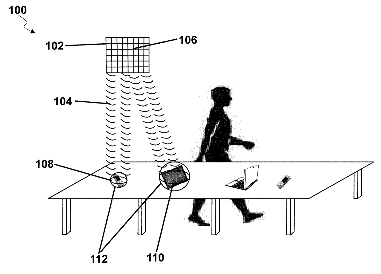
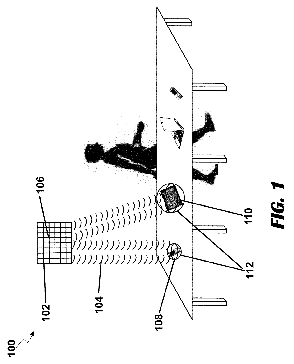
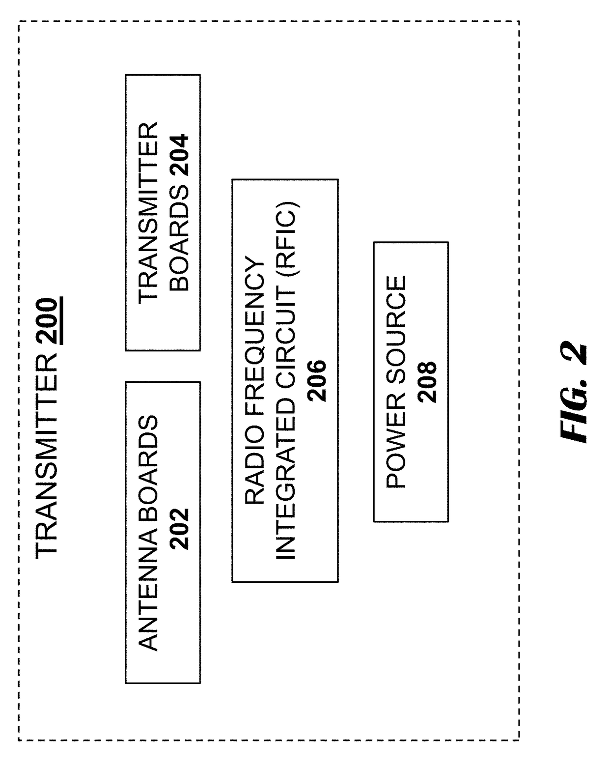
[0030]In a wireless power transmission system, the transmitters are devices that comprise, or are otherwise associated with, various components and circuits responsible for, e.g., generating and transmitting power waves, forming pockets of energy at locations in a transmission field, monitoring the conditions of the transmission field, and generating null spaces where needed. The transmitter may ...


PUM


Abstract

A wireless power transmission system includes a transmitter configured to transmit power waves including printed circuit boards where a printed circuit board and antenna boards, where each antenna board comprises one or more antenna elements, at least one antenna board resides on a printed circuit board, and the at least one antenna board is connected with a power feeding line. The transmitter further includes a heat sink attached to the at least one printed circuit board, wherein placement of the heat sink with respect to the at least one antenna board comprising the one or more antenna elements and shape of the heat sink is configured such that the heat sink operates as a reflector to direct wireless power waves transmitted from the at least one antenna board in a pre-determined direction.

Description

CROSS-REFERENCE TO RELATED APPLICATIONS[0001]This non-provisional application claims the benefit of U.S. Provisional Patent Application Ser. No. 62 / 272,427, entitled “Modular Antennas in Wireless Power Transmission Systems,” filed Dec. 29, 2015, and U.S. Provisional Patent Application Ser. No. 62 / 273,204, entitled “Modular Antennas in Wireless Power Transmission Systems,” filed Dec. 30, 2015, each of which is incorporated by reference in its entirety.TECHNICAL FIELD[0002]This application generally relates to wireless power transmission systems and antenna components used in such systems.BACKGROUND[0003]Electronic devices, such as laptop computers, smartphones, portable gaming devices, tablets, or others, require power to operate. This state of being may entail having to charge electronic equipment at least once a day, or in high-use or power-hungry electronic devices, more than once a day. Such activity may be tedious and may present a burden to some users. For example, a user may b...

Claims


Application Information

Patent Timeline
Patent Type & Authority Applications(United States)
IPC IPC(8): H02J50/20
CPCH02J50/20H01Q1/02
Inventor LEABMAN, MICHAEL A.
Owner ENERGOUS CORPORATION
Why Eureka
Try Eureka