
Through-the-earth emergency radio system

a radio system and earth-based technology, applied in emergency/hazardous communication services, modulated carrier systems, wireless communication services, etc., can solve the problem of inability to launch electromagnetic plane waves in this frequency band using conventional antenna structures, and the existing communications system that may have been in place is usually no longer operational, etc. problem, to achieve the effect of tolerating a high level of man-made electromagnetic nois

Active Publication Date: 2017-06-29
VITAL ALERT COMM
View PDF6 Cites 5 Cited by
  • Summary
  • Abstract
  • Description
  • Claims
  • Application Information

AI Technical Summary

Benefits of technology

This patent describes a way to send wireless signals through the earth using a very low magnetic or electric field. The technology can be handheld and used for emergency communications, and it is resistant to interference from power lines and equipment. This system does not require long antennas, is safe in hazardous conditions, and can still communicate through the earth even when there is a lot of power line noise.

Problems solved by technology

In this type of event, any existing communications system that may have been in place is usually no longer operational.
Electromagnetic plane waves cannot be launched in this frequency band using conventional antenna structures due to the extremely large wavelengths of the signals involved.
Both these techniques generally require one or more wires to be deployed to create a loop antenna or connect to the electrodes, with lengths >30 m typical for operation to depths of 100 m. This is not practical in an emergency situation, where the space may be limited and the transmit antenna wires may be damaged during operations.
In the presence of water or hazardous atmospheres, the transmit antenna wires may also present a safety hazard due to the high currents and voltages used.
The installation of electrodes for current injection is also not practical for equipment that must be portable and rapidly deployed.
In addition, in urban areas, the ULF frequency band also contains a large amount of man-made electromagnetic noise, created by electrical machinery and power lines.
This noise is encountered above ground and below ground and will be present after an emergency, emanating from power lines unaffected by the event.

Method used


Image

  • Through-the-earth emergency radio system
  • Through-the-earth emergency radio system
  • Through-the-earth emergency radio system

Examples


Embodiment Construction

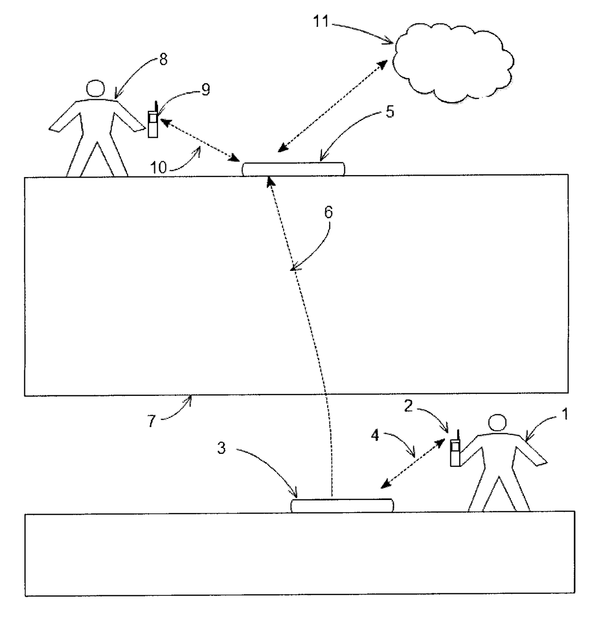
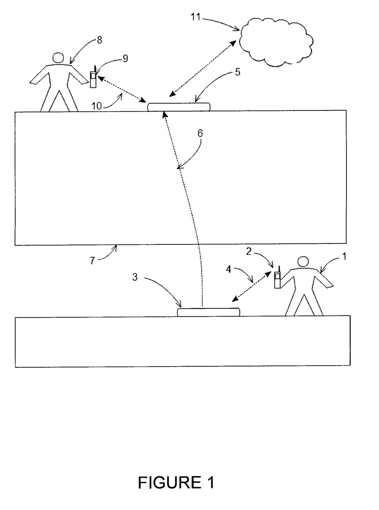
[0023]In one embodiment, a Through-the-Earth Emergency Radio (TER) is used at each end of a Through-the-Earth (TTE) communications link to provide communication between a surface and a location below the earth. FIG. 1 is a system level diagram of this configuration. A below ground worker 1 uses a mobile radio 2 to send voice or text data to TER 3, which is located below ground, over a conventional radio link 4. The TER 3 sends the voice and data information to a second TER 5 which is located on the surface by means of a TTE link 6 provided by a modulated magnetic field. The frequency of the modulated magnetic field 6 is such that it is able to penetrate the overburden 7, and may typically be in the range 800 Hz to 4000 Hz. TER 5 then transmits the voice and data information to a worker 8 located at the surface via a second radio 9 and conventional wireless link 10. The data may also be transmitted into a voice or data network 11.

[0024]Magnetic induction may be used for the TTE link ...


PUM


Abstract

There is provided a Through the Earth Emergency Radio (TER) method and apparatus for creating a communications link that can penetrate the earth or other thick, solid barriers. The communication link is used to connect mobile radios or other conventional wireless devices located below ground and on the surface. The through the earth communication link uses a multi-carrier modulation method that minimizes the impact of AC power line noise by locating each carrier between the harmonic frequencies of the AC power line noise.

Description

TECHNICAL FIELD[0001]The present invention relates to the field of through-the-Earth (TTE) communications and more specifically, to TTE systems for use during emergency situations.INTRODUCTION[0002]In an emergency situation such as the aftermath of a fire or explosion in a subway tunnel or other structure below ground, there is a need for emergency workers to enter the tunnel and perform rescue and fire-fighting work. In this type of event, any existing communications system that may have been in place is usually no longer operational. In order to coordinate the work and ensure the safety of the emergency workers, it is highly desirable for them to have a communications link to the surface. Through-the-Earth (TTE) communications systems are capable of communicating through solid rock and other solid material, for example the overburden above a subway tunnel. This overburden may typically consist of material including various types of rock, clay, sand, gravel and concrete, some of wh...

Claims


Application Information

Patent Timeline
Patent Type & Authority Applications(United States)
IPC IPC(8): H04B13/02H01Q1/22H04W4/22H01Q7/00H04B1/034H04L27/26H04W4/90
CPCH04B13/02H04B1/034H04L27/2602H04B1/3827H01Q7/00H01Q1/2291H04W4/22H04B1/38H04B1/40H04L27/26H01Q1/273H04L25/4902H04W4/90
Inventor ROPER, MICHAEL JAMESKWASNIOK, PETERPUZAKOV, VLADIMIR
Owner VITAL ALERT COMM
Learn More