
Portable self-contained modular power rack

Inactive Publication Date: 2017-07-06
MARTIN STEPHEN THOMAS RIDGWAY
View PDF37 Cites 55 Cited by
  • Summary
  • Abstract
  • Description
  • Claims
  • Application Information

AI Technical Summary

Benefits of technology

The present invention is a portable power rack assembly that can be adjusted in height, width, and depth to work with any barbell lift and weightlifting equipment. The assembly includes a first upright subassembly, a second upright subassembly, a third upright subassembly, and a fourth upright subassembly. The assembly also includes a first lateral subassembly, a second lateral subassembly, a third lateral subassembly, and a fourth lateral subassembly. The assembly includes a mounting bracket with a spring tab and a weight safety catch. The assembly allows for easy adjustment of the power rack's height, width, and depth. The telescoping subassemblies and the lateral subassemblies enable the adjustment of the power rack's width and depth. The assembly is portable and self-contained, making it easy to move and adjust.

Problems solved by technology

However, existing racks are typically large and expensive pieces of equipment, often prohibitive to ownership in the cost of both materials and shipping.
Additionally, existing power racks do not provide the lifter with sufficient space to perform common weightlifting maneuvers such a forward barbell lunge, do not work in conjunction with weight benches with attached barbell racks, and do not work in conjunction with smaller weightlifting bars, such as curl bars (i.e., EZ bars, hammer bars and hex bars), or other specialty bars (i.e., modified squat bars, cambered bars, and multi-grip bars).

Method used


Image

  • Portable self-contained modular power rack
  • Portable self-contained modular power rack
  • Portable self-contained modular power rack

Examples


Embodiment Construction

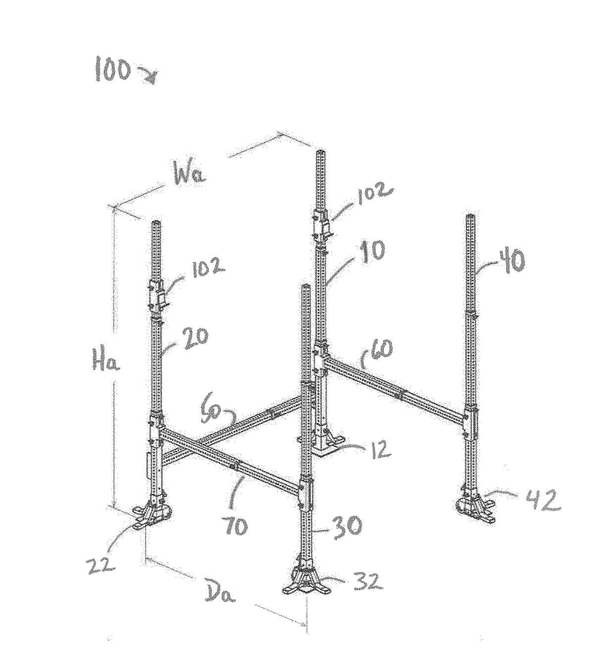
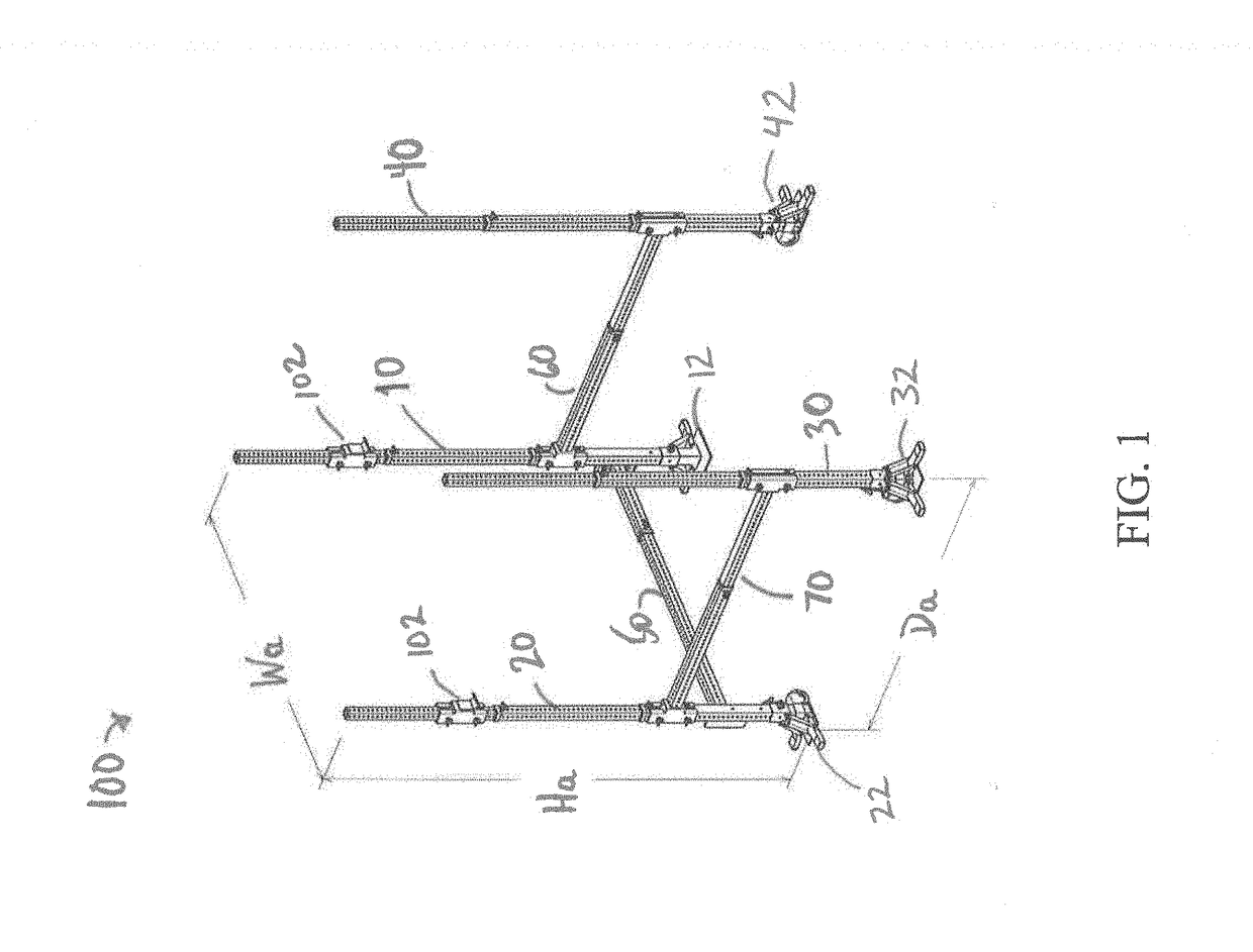
[0050]One embodiment of a portable, self-contained modular weight catch safety rack of the present invention provides a power rack that can be readily moved and adjusted telescopically in height, width and depth to work in conjunction with any barbell lift and any weightlifting equipment. The power rack of the present is of substantially less size and weight compared to existing power racks, thereby reducing the cost of shipping and materials while also allowing for the power rack to be readily assembled and disassembled, transported and stored. The power rack of the present invention is width-adjustable, depth adjustable and height adjustable. In addition, the power rack of the present invention provides a portable self-contained case that can be converted into a fully functional weightlifting bench, mattress, bench, table, or the like.

[0051]One embodiment of portable, self-contained modular weight catch safety rack of the present invention is a power rack as shown in FIG. 1 and is...


PUM


Abstract

A power rack adjustable telescopically in height, width and depth to work in conjunction with any barbell lift and any weightlifting equipment a first upright subassembly, a second upright subassembly, a third upright subassembly and a fourth upright subassembly. A first lateral subassembly is releasably connected to the first and second upright subassemblies. A second lateral subassembly is releasably connected to the first and fourth upright subassemblies. A third lateral subassembly is releasably connected to the second and third upright subassemblies. A weight safety catch is releasably mounted on each of the first and second upright subassemblies. The first and second upright subassemblies define an adjustable height of the power rack, the first lateral subassembly defines an adjustable width of the power rack, and the second and third lateral subassemblies define an adjustable depth of the power rack.

Description

CROSS REFERENCE[0001]This application claims the benefit of the following four co-pending U.S. provisional patent applications, the contents of each of which are incorporated herein by reference in their entirety:[0002](i) U.S. Provisional Patent Application No. 62 / 275,003 filed on Jan. 5, 2016;[0003](ii) U.S. Provisional Patent Application No. 62 / 297,894 filed on Feb. 21, 2016;[0004](iii) U.S. Provisional Patent Application No. 62 / 302,856 filed on Mar. 3, 2016; and[0005](iv) U.S. Provisional Patent Application No. 62 / 339,855 filed on May 21, 2016.FIELD OF THE INVENTION[0006]The present invention is directed to a racking system having a barbell or weight catch feature for safely performing exercises with a barbell or weightlifting bar. More particularly, the present invention is directed to a portable, self-contained modular weight catch safety rack for performing exercises with a barbell or weightlifting that can be readily moved and adjusted telescopically in height, width and dep...

Claims


Application Information

Patent Timeline
IPC IPC(8): A63B21/078A63B21/00
CPCA63B21/0783A63B2225/093A63B21/4029A63B17/04A63B21/078A63B23/1218A63B71/0036A63B71/028A63B2071/025A63B2210/50A63B2225/09A63B21/169F16B7/105E04H12/22
Inventor MARTIN, STEPHEN THOMAS RIDGWAY
Owner MARTIN STEPHEN THOMAS RIDGWAY
Features
  • Generate Ideas
  • Intellectual Property
  • Life Sciences
  • Materials
  • Tech Scout
  • Unparalleled Data Quality
  • Higher Quality Content
  • 60% Fewer Hallucinations
Learn More