Coil making apparatus and method

Active Publication Date: 2017-07-06
CURTI COSTR MECCANICHE
View PDF1 Cites 0 Cited by
  • Summary
  • Abstract
  • Description
  • Claims
  • Application Information

AI Technical Summary

Benefits of technology

The patent text describes a way to adjust the size of a cable so that its ends are in a specific position. This allows for automatic processing of the ends without the need for manual intervention. The technical effect of this is that it provides a more efficient and streamlined process for cable installation.

Problems solved by technology

It is known to make coils by winding the cable or wire into a drum-like cavity of a non-rotating winding apparatus, as disclosed e.g. by DE 42 35 007; this method is not suitable for preparing coils with ends ready for further processing, also because it is not possible to control the radius of curvature of the cable.
In fact, one problem faced by the known methods and apparatuses is to provide a required length for the two cable ends for further processing of the cable at its two ends.
Actually, changing the diameter of the coil during the forming of the coil is a step very difficult to achieve, especially once a couple of windings have been provided on the coil former.
Another problem of this document is that the cable (or wire) has to be cut into the desired length in advance; a cut cable may be difficult to handle, especially if the cable is longer than a few meters, e.g. longer than 3-4 meters.

Method used


Image

  • Coil making apparatus and method
  • Coil making apparatus and method
  • Coil making apparatus and method

Examples


Embodiment Construction

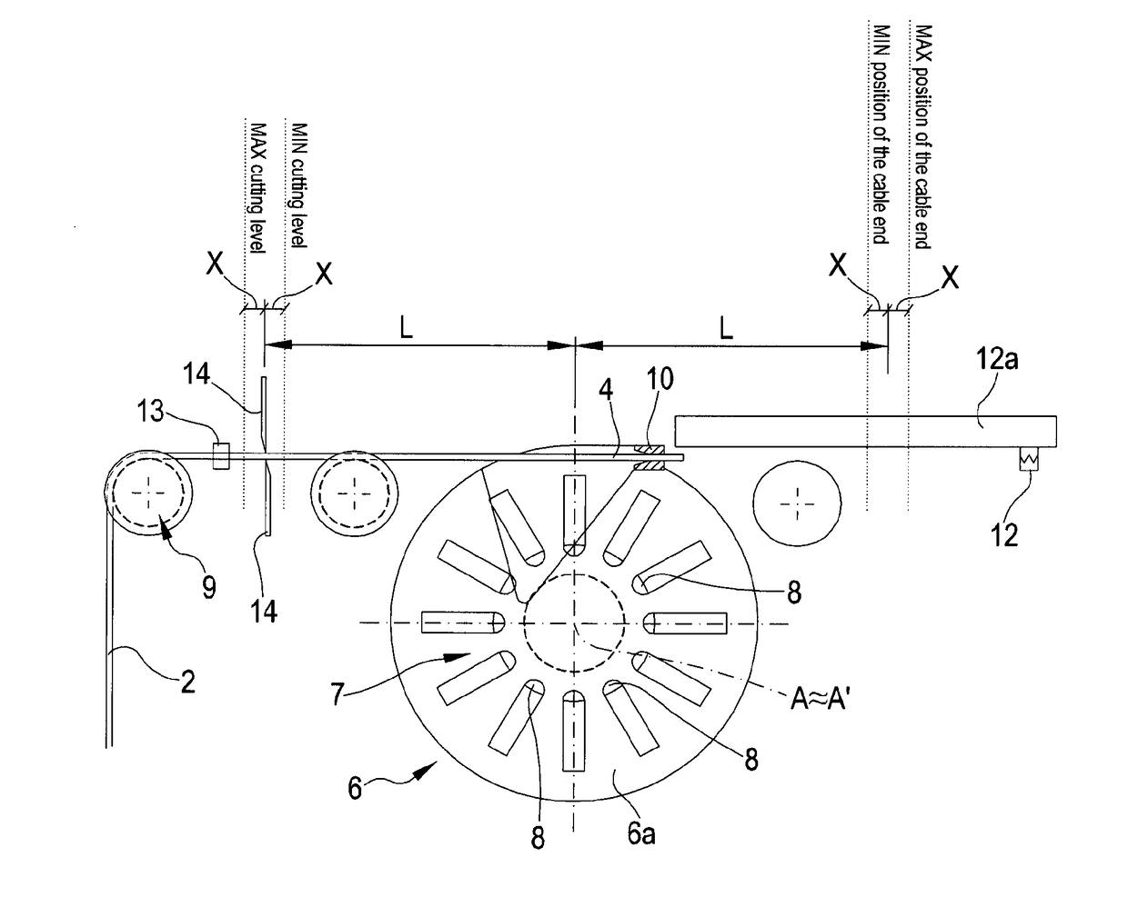
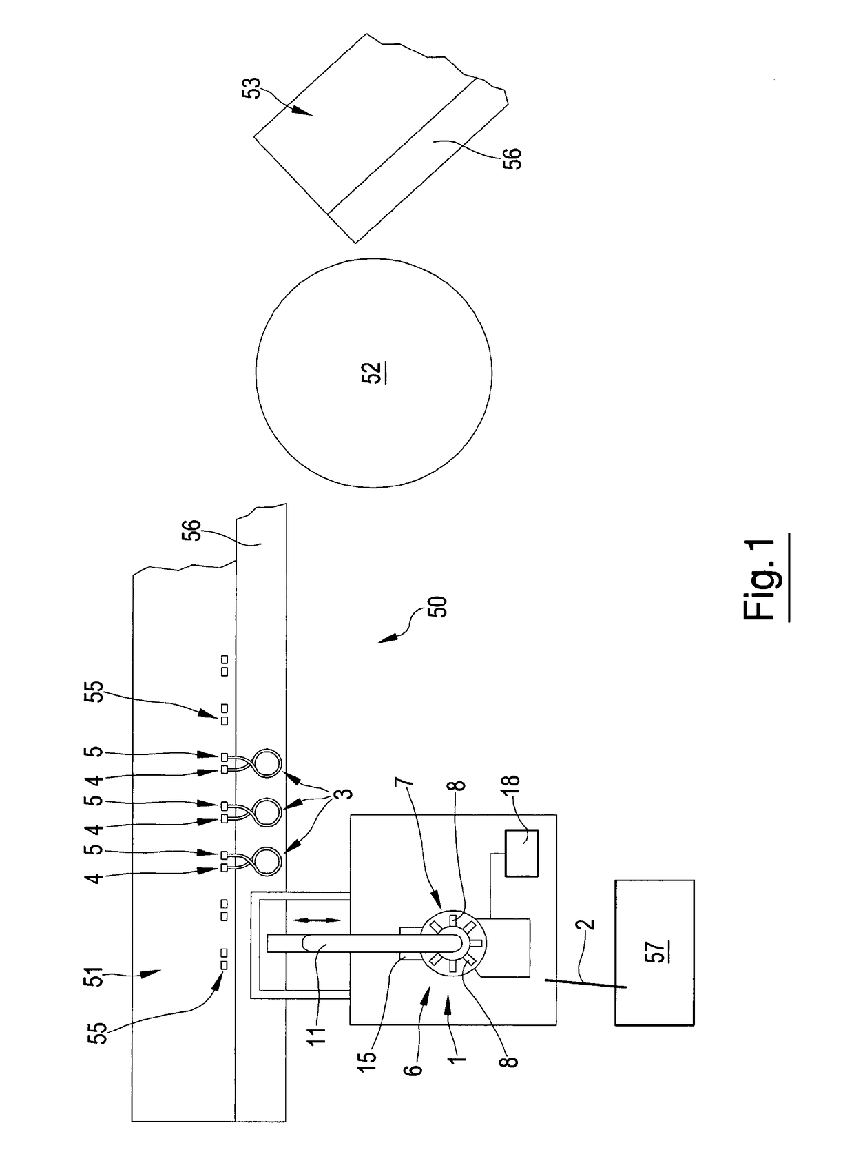
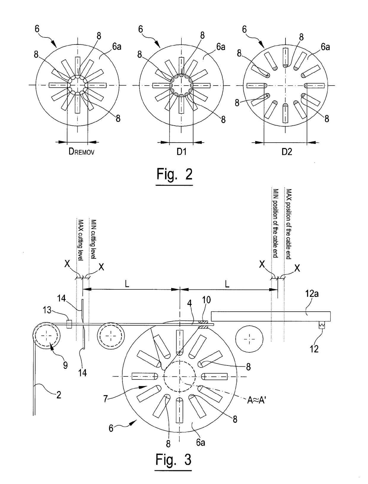
[0025]As shown in the figures, according to a possible embodiment of the apparatus 1 for coiling a cable 2, or a wire, into a coil 3, it comprises a rotatable coil former 6 around which a cable is coiled (wound) to form a plurality of turns 3a and two free ends 4, 5, formed by a leading end 4 and a trailing end 5 of the cable 2.

[0026]It has to be noted that in the following the term “free ends” is used to indicate the trailing end and leading end, in fact, the free ends of the coil are formed by a leading end of the cable and a trailing end of the cable.

[0027]The cable 2 intended to be coiled can be supplied, preferably continuously, in a known way from one or more reels 57, or other supply means not shown in the figures.

[0028]The apparatus 1 further comprises means 9 to measure the length of the coiled cable 2 or wire, which are known in the art. The means 9 measure the length of the cable 2 supplied to the coil former 6, and preferably the cable length passing cutting means 14 of ...


PUM


Abstract

An apparatus (1) and a method for coiling a cable (2) or a wire into a coil (3) having a plurality of turns (3a) and two free ends (4, 5) formed by a leading end (4) and a trailing end (5) of said cable are disclosed. The apparatus comprises a rotatable coil former (6) around which a cable is coiled; means (9) to measure the length of the coiled cable (2) or wire; first holding means (10) positioned on said coil former (6) for holding the leading end (4) of the cable, second holding means (12), separate from said coil former (6) for receiving and holding the leading end (4) of the cable (2), which are movable. Cutting means (14) for cutting the coiled cable to provide a trailing end (5) of the cable are also provided. The apparatus further comprises means (7) to adjust the diameter (D1, D2) of the coil former (6) and control means (18) to set said adjusting means (7) of the diameter of the coil former (6), to provide the required length of the cable and the required length of the said free ends (4, 5) of the coiled cable.

Description

FIELD OF THE INVENTION[0001]The present invention relates to a coil making apparatus and method, in particular, to an apparatus and a method for coiling a cable or wire or similar conducting devices, to provide a coil having two free ends that can be processed.BACKGROUND ART[0002]It is known to wind cables or wires into coils for further storing, shipping or further processing. It is known to make coils by winding the cable or wire into a drum-like cavity of a non-rotating winding apparatus, as disclosed e.g. by DE 42 35 007; this method is not suitable for preparing coils with ends ready for further processing, also because it is not possible to control the radius of curvature of the cable. The radius of curvature can be controlled by using a coil forming apparatus where the cable is wound around a coil former; once the coil has been formed around the forming nucleus, the former's diameter is decreased to allow safe removal of the coil.[0003]In fact, one problem faced by the known ...

Claims


Application Information

Patent Timeline
IPC IPC(8): B65H54/62B65H63/08
CPCB65H63/08B65H54/62B65H54/58B65H54/71B65H2701/34B65H2701/36B65H61/00
Inventor BOCCATO, ENRICO
Owner CURTI COSTR MECCANICHE
Why Eureka
Try Eureka