

Expansion Joint for Longitudinal Load Transfer
a technology of expansion joints and longitudinal loads, applied in single-unit pavings, bridges, roads, etc., can solve the problems of system failure, system failure to meet the resiliency and seismic movement requirements of expansion joints, and joint damage,
- Summary
- Abstract
- Description
- Claims
- Application Information
AI Technical Summary
Benefits of technology
Problems solved by technology
Method used
Image

Examples
Embodiment Construction
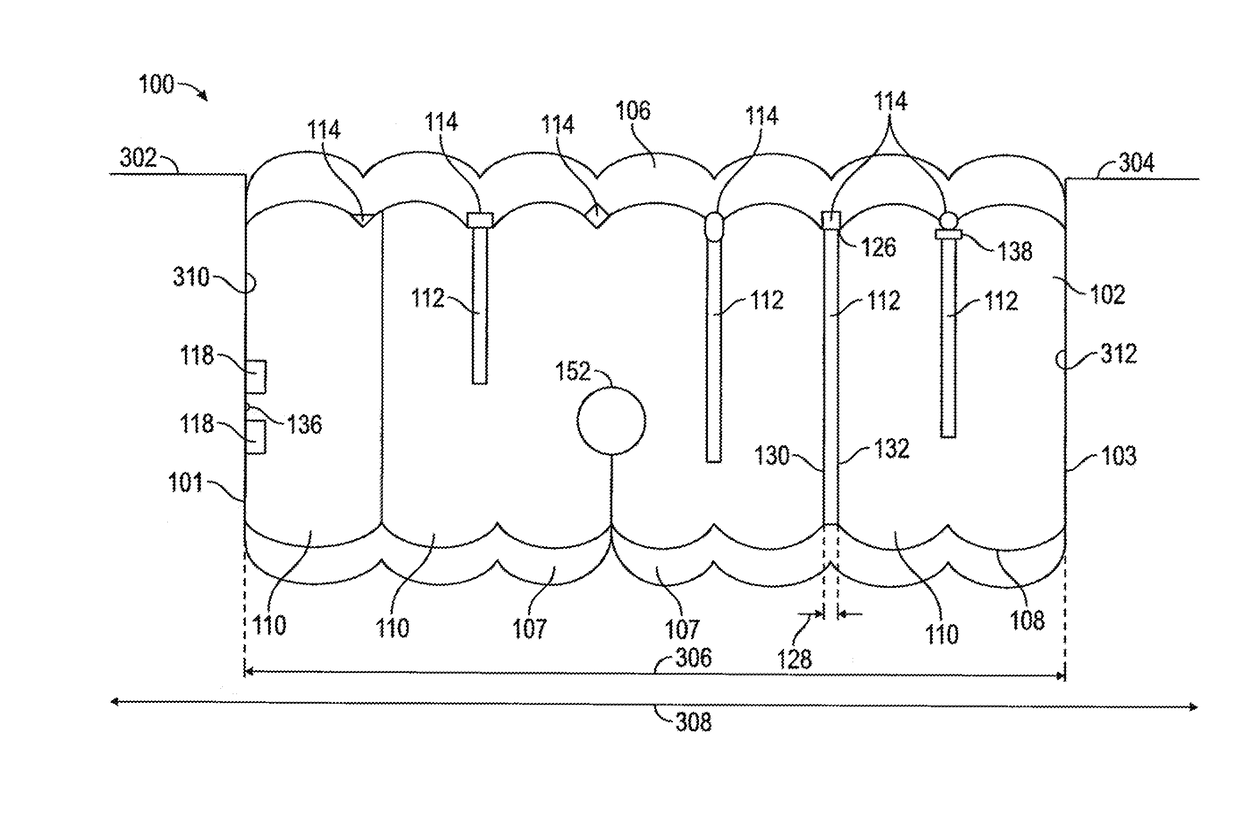
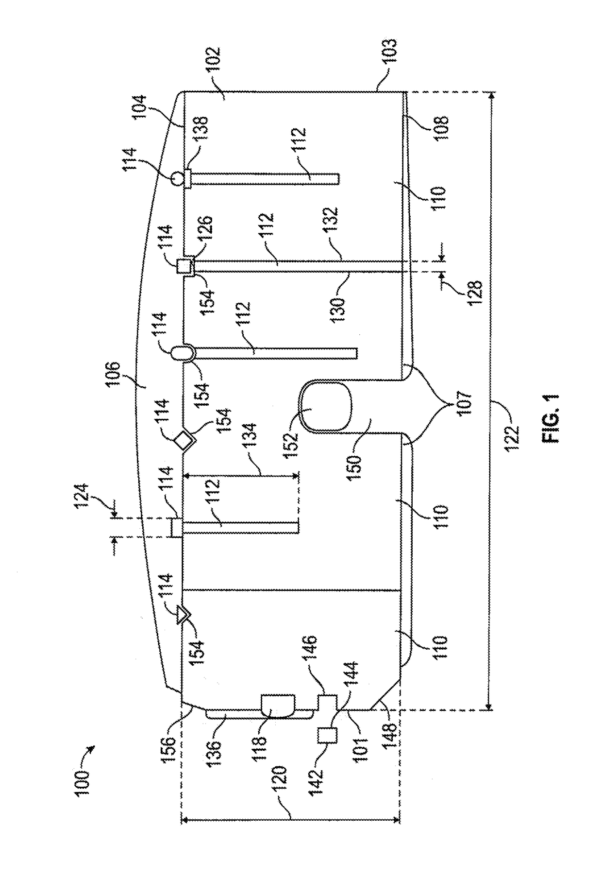
[0016]Referring to FIG. 1, an end view of one embodiment of the expansion joint system 100 of the present disclosure is provided. The system includes an elongated core 102 and at least one longitudinal load-transfer member 114 which are bonded together.
[0017]The elongated core 102 is composed of resiliently compressible foam, which may he closed cell or open cell foam, or a combination thereof. The extent of compressibility may be selected based on the need. A higher compression results in higher water resistance, but may create difficulties in installation, and ultimately becomes so compressed as to lack flexibility, such as at a ratio of 5:1. The elongated core 102 may be compressible by 25%, or may compress by 100% or as high as 400% so that the elongated core 102 is one quarter of the elongated core lateral width 122. However, the higher compression ratios negatively affect the functionality of the system 100 by, among other issues, reducing the movement of the system 100 within...
PUM
| Property | Measurement | Unit |
|---|---|---|
| compression ratios | aaaaa | aaaaa |
| compression ratios | aaaaa | aaaaa |
| height | aaaaa | aaaaa |
Abstract
Description
Claims
Application Information