Door latch assembly

a door latch and assembly technology, applied in the direction of building locks, constructions, construction fastening devices, etc., can solve the problems of increased manufacturing procedures and/or cost, and achieve the effects of improving and simplifying structure or configuration, easy and quick assembly, and easy and quick manufacturing or production

Inactive Publication Date: 2017-07-06
THASE ENTERPRISE CO LTD
View PDF0 Cites 7 Cited by
  • Summary
  • Abstract
  • Description
  • Claims
  • Application Information

AI Technical Summary

Benefits of technology

[0008]The primary objective of the present invention is to provide a door latch assembly including an improved and simplified structure or configuration for allowing the door latch assembly to be easily and quickly assembled by the workers and for allowing the door latch assembly to be easily and quickly made or manufactured with a reduced making or manufacturing procedure and / or cost and to be easily and quickly assembled by the workers or the like.

Problems solved by technology

However, the upper and the lower latch devices of the door latch assembly should be actuated or operated by a complicated connecting or coupling mechanism, in addition, the upper and the lower latch devices of the door latch assembly also include a complicated connecting or coupling mechanism, such that the making or manufacturing procedures and / or the cost may be greatly increased.

Method used


Image

  • Door latch assembly
  • Door latch assembly
  • Door latch assembly

Examples


Embodiment Construction

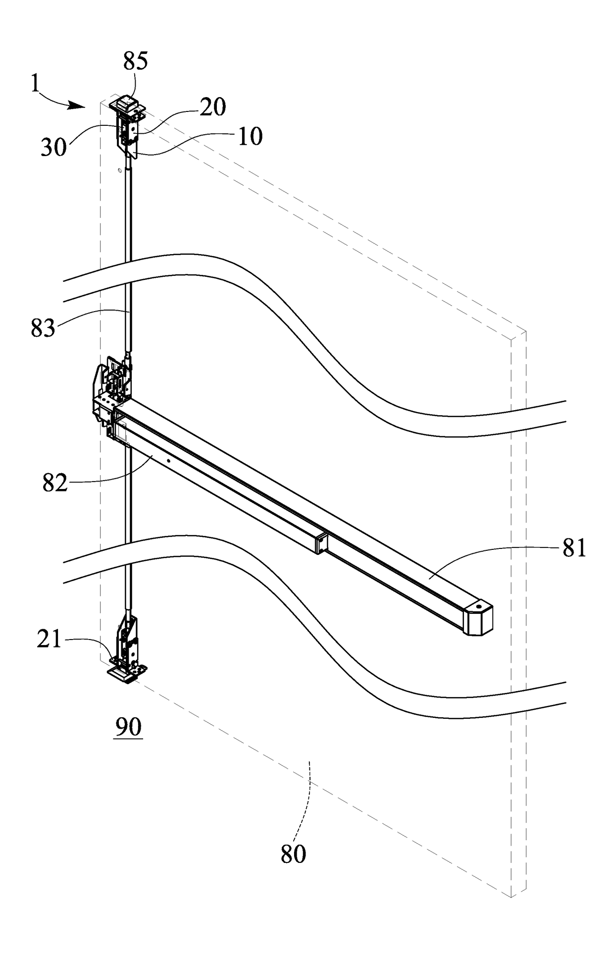
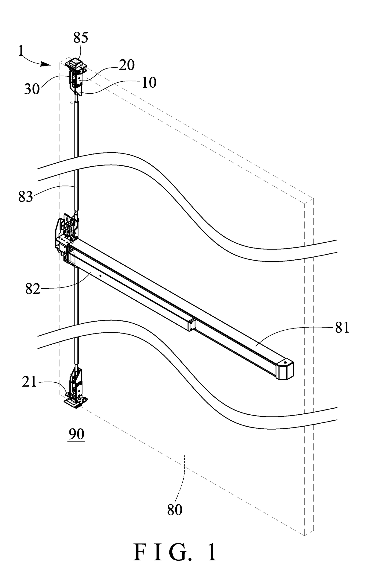
[0021]Referring to the drawings, and initially to FIGS. 1-6, a door latch assembly in accordance with the present invention comprises a latch mechanism including one or more (such as two) transmitting or latch devices 1 disposed or engaged into a door panel 80, such as an exit door panel 80 that is disposed or engaged into a door frame 86, and preferably arranged or located at one side or edge portion of the door panel 80 (FIG. 1), and mounted or secured to the door panel 80 with screws or catches or fasteners (not illustrated) or the like, and as shown in FIGS. 1 and 7, the door panel 80 includes a box or casing 81 attached or mounted to the inner or indoor portion of the door panel 80, and a push bar 82 slidably attached or mounted to the casing 81 and connected or coupled to the latch devices 1 with one or more (such as two) actuating levers 83 for selectively actuating or operating the actuating levers 83 to actuate or operate the latch devices 1 of the latch mechanism.

[0022]One...


PUM


Abstract

A door latch assembly includes two receptacles mounted to a door panel and spaced from each other, two latchbolts pivotally attached to the receptacles for engaging with strikes and for locking the door panel to a door frame, two sliding members slidably engaged in the receptacles and each having a protrusion for engaging with the latchbolts, two spring biasing members engaged between the sliding members and the receptacles for biasing the sliding members toward the strikes, and two actuating levers connected between the sliding members and a push bar for allowing the sliding members to be moved away from the latchbolts by the push bar with the actuating levers selectively.

Description

BACKGROUND OF THE INVENTION[0001]1. Field of the Invention[0002]The present invention relates to a door latch assembly for a panic exit door, and more particularly to a door latch assembly for a panic exit door including an improved and simplified structure or configuration for allowing the door latch assembly to be easily and quickly made or manufactured with a reduced making or manufacturing procedure and / or cost and to be easily and quickly assembled by the workers or the like.[0003]2. Description of the Prior Art[0004]Various kinds of typical door latch assemblies for panic exit doors have been developed and provided for latching or locking the exit doors and comprise a push bar connected or coupled to a door latch assembly for actuating or operating the door latch assembly to lock and release the exit doors.[0005]For example, U.S. Pat. No. 5,464,259 to Cohrs et al., U.S. Pat. No. 6,009,732 to Haeck et al., and U.S. Patent Application Publication No. 2012 / 0032455 A1 to Lin discl...

Claims


Application Information

Patent Timeline
Patent Type & Authority Applications(United States)
IPC IPC(8): E05B65/10E05C3/24
CPCE05B65/1006E05B65/1046E05C3/24E05B65/1053
Inventor LIN, CHING TIEN
Owner THASE ENTERPRISE CO LTD
Why Eureka
Try Eureka