Spinal plate assembly having locking mechanism

a technology of locking mechanism and spine, which is applied in the field of spine plates, can solve the problems of ineffective locking mechanism, unnecessarily expensive, and complicated application, and achieve the effects of convenient fixing screws, convenient locking mechanism, and convenient removal and readingjustmen

Active Publication Date: 2017-07-13
GLOBUS MEDICAL INC
View PDF7 Cites 29 Cited by
  • Summary
  • Abstract
  • Description
  • Claims
  • Application Information

AI Technical Summary

Benefits of technology

[0005]The present invention cures some of the deficiencies in the prior art by providing a spinal plate assembly having an improved locking mechanism for conveniently fixing screws in a locked position without the need for cumbers

Problems solved by technology

However, many of these locking mechanisms are ineffective, cumbersome, complicated and time consuming to apply, and unnecessarily expensive.
In addition, many of these locking mechanisms are unable to provide convenient manipulation and readjustment of the bone screws and plate during rev

Method used


Image

  • Spinal plate assembly having locking mechanism
  • Spinal plate assembly having locking mechanism
  • Spinal plate assembly having locking mechanism

Examples


Embodiment Construction

Rotating Member and Flexible Element and Annular Groove

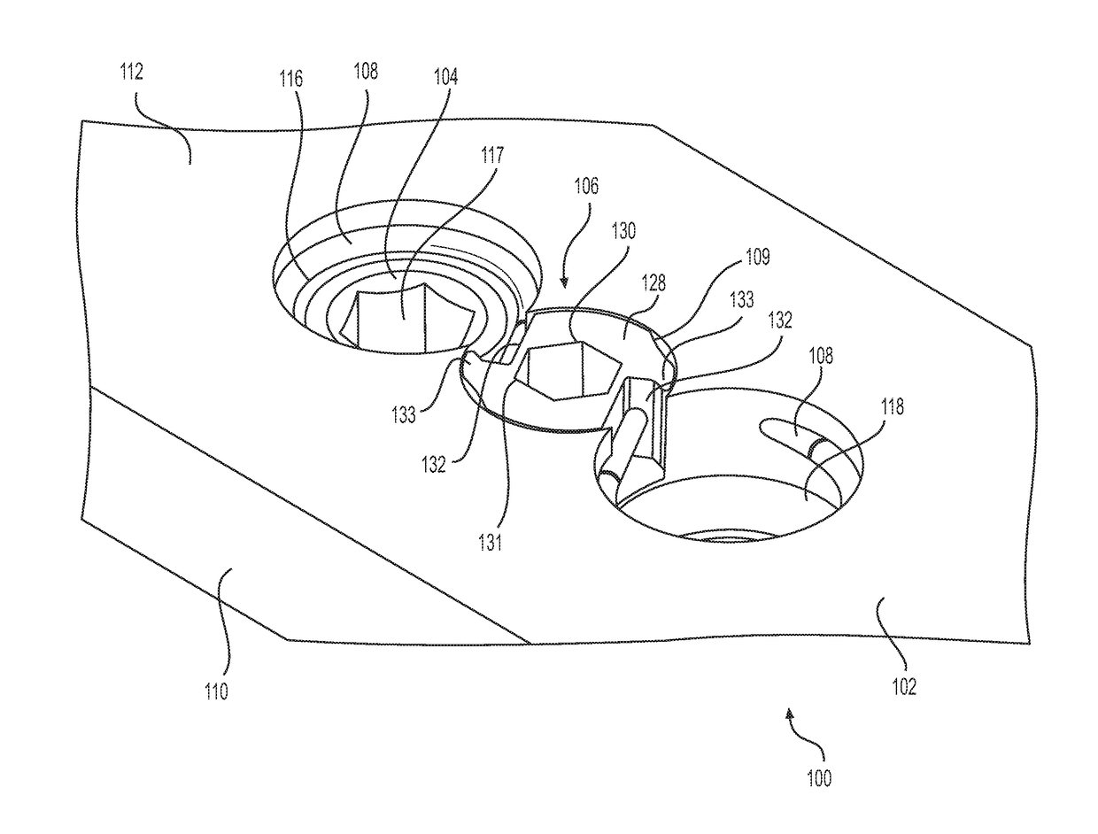
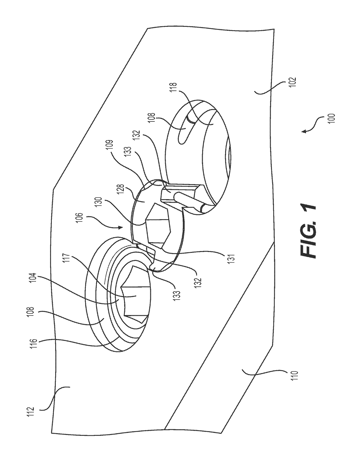
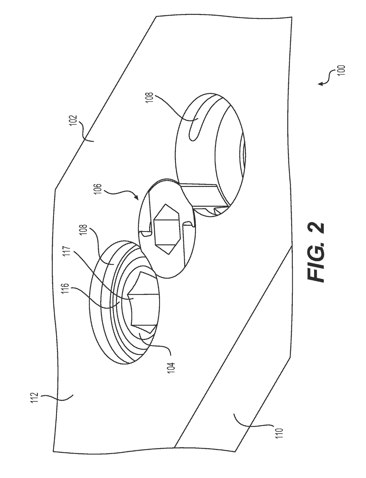
[0032]FIG. 1 is a perspective view of the spinal plate assembly 100 in a “locked” condition according to an illustrative embodiment of the present invention. FIG. 2 is a perspective view of the spinal plate assembly 100 in an “unlocked” condition according to an illustrative embodiment of the present invention. The spinal plate assembly 100 in these figures comprises: base plate 102, bone screw 104, locking mechanism 106, and aperture 108. The base plate 100 of the illustrative embodiment is preferably constructed from a biocompatible plastic, metal, metal alloy, or a combination thereof. The biocompatible metals and metal alloys can be, for example, and without limitation, titanium, titanium alloy, stainless steel, cobalt chrome, or any combination thereof. However, it will be clear to those skilled in the art, after reading this disclosure, how to make and use alternative embodiments in which some of the elements of base plate...


PUM


Abstract

A spinal plate assembly comprising a base plate defining an opening adjacent at least one aperture for receiving a bone screw which attaches to a spinal vertebrae. The aperture includes a seat and an annular groove having an end wall. The assembly comprises a locking mechanism having a split ring partially recessed within the annular groove and moveable between a locked condition partially blocking the aperture for retaining the screw in the seat and an unlocked condition radially deformable into the annular groove for permitting screw removal. The split ring has a proximal end and a distal end. The distal end is configured to engage the end wall of the annular groove. The locking mechanism comprises a rotating member retained within the opening of the base plate and having a notch configured to engage the proximal end of the ring to drive the ring toward the unlocked condition.

Description

FIELD OF THE INVENTION[0001]The present invention relates generally to spinal plates used for fusing vertebrae in the treatment of spinal disorders, and more particularly to an improved locking mechanism within the plate assembly for securing bone screws in position after insertion and allowing for easy removal and readjustment.BACKGROUND OF THE INVENTION[0002]For over three decades plates have been used to increase stability of the spine following surgery to promote proper healing of injured or damaged vertebrae caused by disease, trauma, spinal defect, accident or the like. Conventional spinal plates are generally implanted during surgery by mounting to one or more vertebrae using bone screws. These plates often employ a locking mechanism to reduce the likelihood of screws disconnecting, reverse threading, backing out or otherwise puffing away from vertebrae in which they are mounted. Traditional locking mechanism employ securing caps, cover plates, bearings, screws with novel thr...

Claims


Application Information

Patent Timeline
IPC IPC(8): A61B17/80A61B17/86A61B17/70
CPCA61B17/8052A61B2017/00862A61B17/8615A61B17/7059A61B17/8042A61B17/8605
Inventor CIANFRANI, JASONMORRIS, ROSS
Owner GLOBUS MEDICAL INC
Why Eureka
Try Eureka