Apparatus for Harnessing Flowing Fluids to Create Torque

a technology of fluid flow and torque, applied in mechanical apparatus, sea energy generation, machines/engines, etc., can solve the problems of inability to generate power from both water and wind current, inefficiency and unreliability, and high technology cost, and achieve the effect of scalable and economical, small siz

Inactive Publication Date: 2017-07-13
PTEROFIN
View PDF7 Cites 4 Cited by
  • Summary
  • Abstract
  • Description
  • Claims
  • Application Information

AI Technical Summary

Benefits of technology

[0016]In operation, the gentle oscillation of the one or more wings mimics an animals propulsive wing action, such as a bird or insect wing as it flaps through the air, or fish fins propelling through the water. The apparatus can operate at much slower air-flow rates that traditional radial windmills, and is thus scalable and economical at smaller sizes than required for radial windmills.

Problems solved by technology

Additionally, the technology is expensive, and suffers from a number of other problems, including inefficiency and unreliability.
Currently, fluid flow force-capturing devices are generally incapable of generating power from both water and wind currents.
Windmills will only function with wind, and dams and tidal turbines are restricted to an aqueous environment.
This increases development, deployment, and maintenance costs for these types of devices.
Moreover, the optimization of the existing devices typically require a large surface area of the blades on the turbines, which requires lot of physical space.
Since many regions impose height restriction ordinances, windmills have limited use in populated areas.
Windmills and tidal turbines also suffer efficiency problems on the extreme levels of fluid-flow, either too low or too high.
In low flows, these devices are unable to spin, so no energy can be generated.
In high flows, the devices risk spinning out of control and beyond operational tolerances, and require complicated electronic pitching and braking mechanisms.
If these stabilization systems fail, the device may undergo damage.
Additionally, windmills and tidal turbines can have a negative environmental impact.
Both can be noisy and emit low frequency sounds that harass wildlife, such as insects or fish.
Windmills can also create a strobing flicker as sunlight passes through the blades, which is known to cause seizures in humans and animals.

Method used


Image

  • Apparatus for Harnessing Flowing Fluids to Create Torque
  • Apparatus for Harnessing Flowing Fluids to Create Torque
  • Apparatus for Harnessing Flowing Fluids to Create Torque

Examples


Embodiment Construction

[0057]The Figures (FIGS.) and the following description relate to preferred embodiments by way of illustration only. It should be noted that from the following discussion, alternative embodiments of the structures and methods disclosed herein will be readily recognized as viable alternatives that may be employed without departing from the principles of what is claimed.

[0058]Reference will now be made in detail to several embodiments, examples of which are illustrated in the accompanying figures. It is noted that wherever practicable similar or like reference numbers may be used in the figures and may indicate similar or like functionality. The figures depict embodiments of the disclosed device (or method) for purposes of illustration only. One skilled in the art will readily recognize from the following description that alternative embodiments of the structures and methods illustrated herein may be employed without departing from the principles described herein.

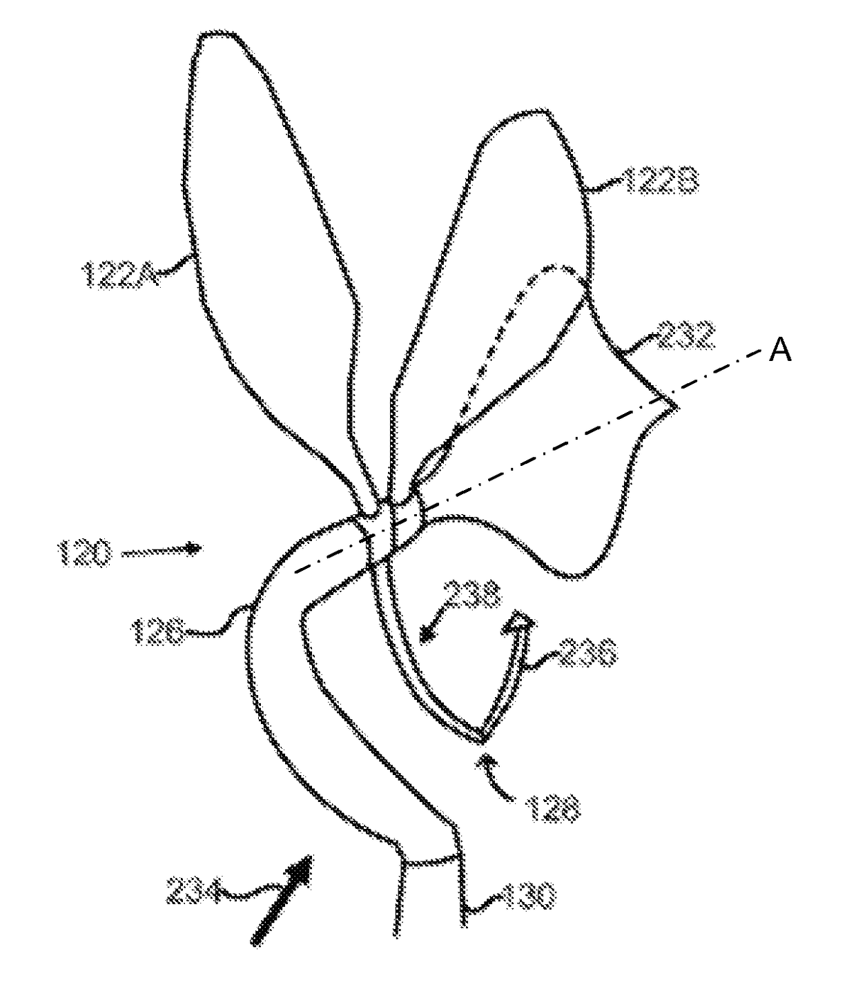
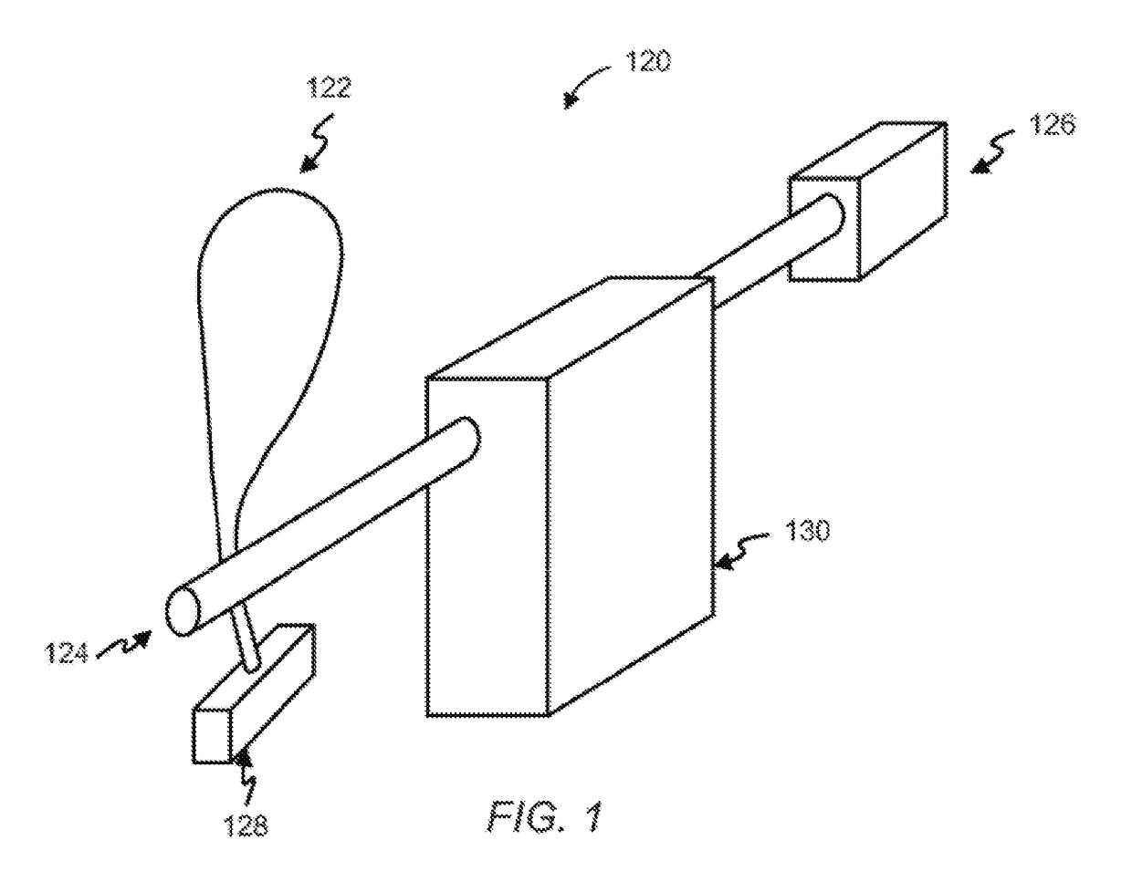
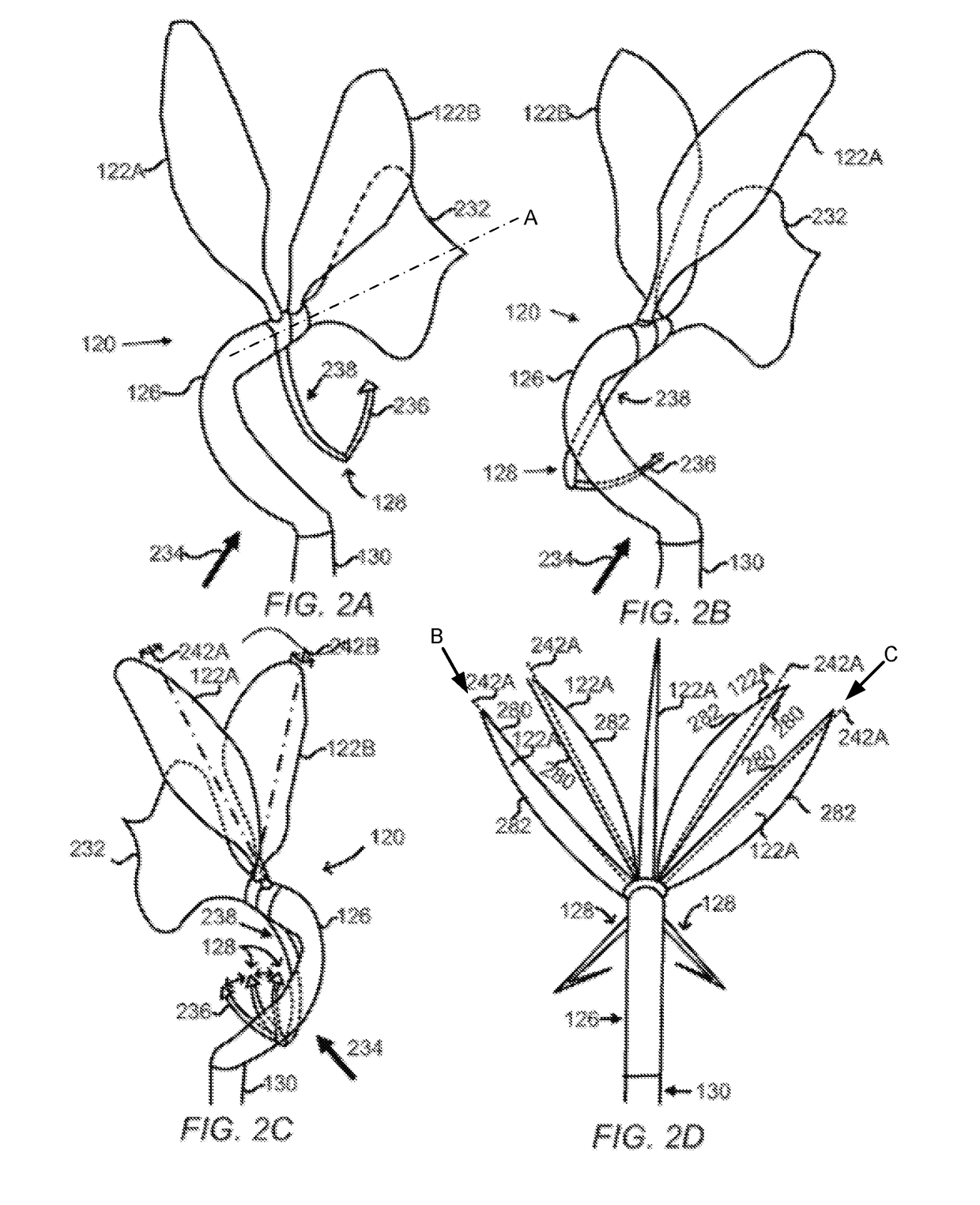
[0059]Illustrated in ...


PUM


Abstract

An apparatus for producing high output and low cost/time, sustainable energy from a fluid flow, such as wind or water natural currents. The apparatus has one or more wings that pivot and change their angle of attack, and oscillate with a counterbalance system that synchronizes the wings' position and speed with a mechanical leverage point on the body of the device. When a fluid flows past the wing, a pendulum causes the wing to constantly change its angle of attack such that the oscillation can harmonizing to the natural frequency of a fluid's specific velocity. The pivoting is translated into mechanical force on a shaft, which then can create torque at a generator or pump.

Description

CROSS-REFERENCE TO RELATED APPLICATIONS[0001]This application is a continuation-in-part of U.S. Utility application Ser. No. 14 / 244,657, filed on Apr. 3, 2014, which is a continuation of U.S. Utility application Ser. No. 13 / 217,170, filed on Aug. 24, 2011, which claims the benefit of U.S. Provisional Application No. 61 / 402,175 filed on Aug. 25, 2010, the entire disclosures of which are hereby incorporated by reference herein in their entirety for all purposes.BACKGROUND[0002]1. Field of the Invention[0003]This invention relates generally to the field of harnessing the energy of moving fluids. More specifically, the present invention is related to apparatuses that can use a force of a flowing fluid, such as air or water, deflecting against components of the apparatus to generate torque.[0004]2. Description of the Related Art[0005]There are a number of products that provide a way of generating electricity from moving fluids, such as windmills, dams, and tidal turbines. These devices c...

Claims


Application Information

Patent Timeline
Patent Type & Authority Applications(United States)
IPC IPC(8): F03D5/06F03G3/06F03D9/25
CPCF03D5/06F03G3/06F03D9/25F03B15/00F03B17/06F03B17/061F03D1/02F03D1/04F05B2210/16F05B2240/13F05B2240/311F05B2260/4031F03D7/02Y02E10/20Y02E10/30Y02E10/70Y02E10/72
Inventor KEMPKEY, WALLACE WRIGHTBREIDENTHAL, ROBERT EDWARD
Owner PTEROFIN
Why Eureka
Try Eureka