Exercise Machine Resistance Adjustment System

a technology of resistance force and adjustment system, applied in the direction of resistance force resistors, gymnastic exercise, sport apparatus, etc., can solve the problems of more complex equipment incorporation, and achieve the effect of efficient adjustment of the amount of resistance for

Active Publication Date: 2017-07-27
LAGREE TECH INC
View PDF53 Cites 69 Cited by
  • Summary
  • Abstract
  • Description
  • Claims
  • Application Information

AI Technical Summary

Benefits of technology

[0010]An example embodiment is directed to an exercise machine resistance adjustment system. The exercise machine resistance adjustment system includes a frame, a carriage movably positioned on the frame, a spring connected to the carriage to apply a biasing force to the carriage, one or more left projections within the carriage adapted for a left hand of an exerciser to grasp, and one or more right projections within the carriage adapted for a right hand of an exerciser to grasp. The exerciser is able to efficiently adjust the amount of resistance force applied to the carriage by repositioning their hands (or feet) from a first set of projections at a first distance to a second set of projections at a second distance from the first end of the exercise machine.
[0011]Hooke's Law is a principle of physics that states that the force needed to extend a spring by some given distance is proportional to that distance. Therefore, extending the spring further increases the resistance force required to overcome the proportionally higher force, and conversely, reducing the distance that the spring is extended reduces the resistance force required.
[0012]The various embodiments of the present invention provide for body repositioning on an exercise machine as a means to incrementally increase or decrease the workout resistance level without having to interrupt exercising in order to change the type of number of resistance elements against which they are exercising. Some of the various embodiments illustrate positioning pockets or slots sized appropriately to accommodate an exerciser's hands or feet, the features placed at various positions on the slidable or stationary platforms along the longitudinal axis of an exercise machine that uses a slidable platform resistance biased toward one end of the machine. The positioning pockets and slots could be considered analogous to variably positioned rungs on a ladder. By easily moving the hands or feet from one rung to another during mid-exercise, the exerciser can quickly increase or decrease the travel distance of the carriage during any given exercise, and therefore the adjust the exercise resistance without stopping the exercise to add or remove springs.

Problems solved by technology

On the other hand, more complex equipment incorporates a plurality of resistance elements that provide the exerciser with many choices of resistance levels.

Method used


Image

  • Exercise Machine Resistance Adjustment System
  • Exercise Machine Resistance Adjustment System
  • Exercise Machine Resistance Adjustment System

Examples


Embodiment Construction

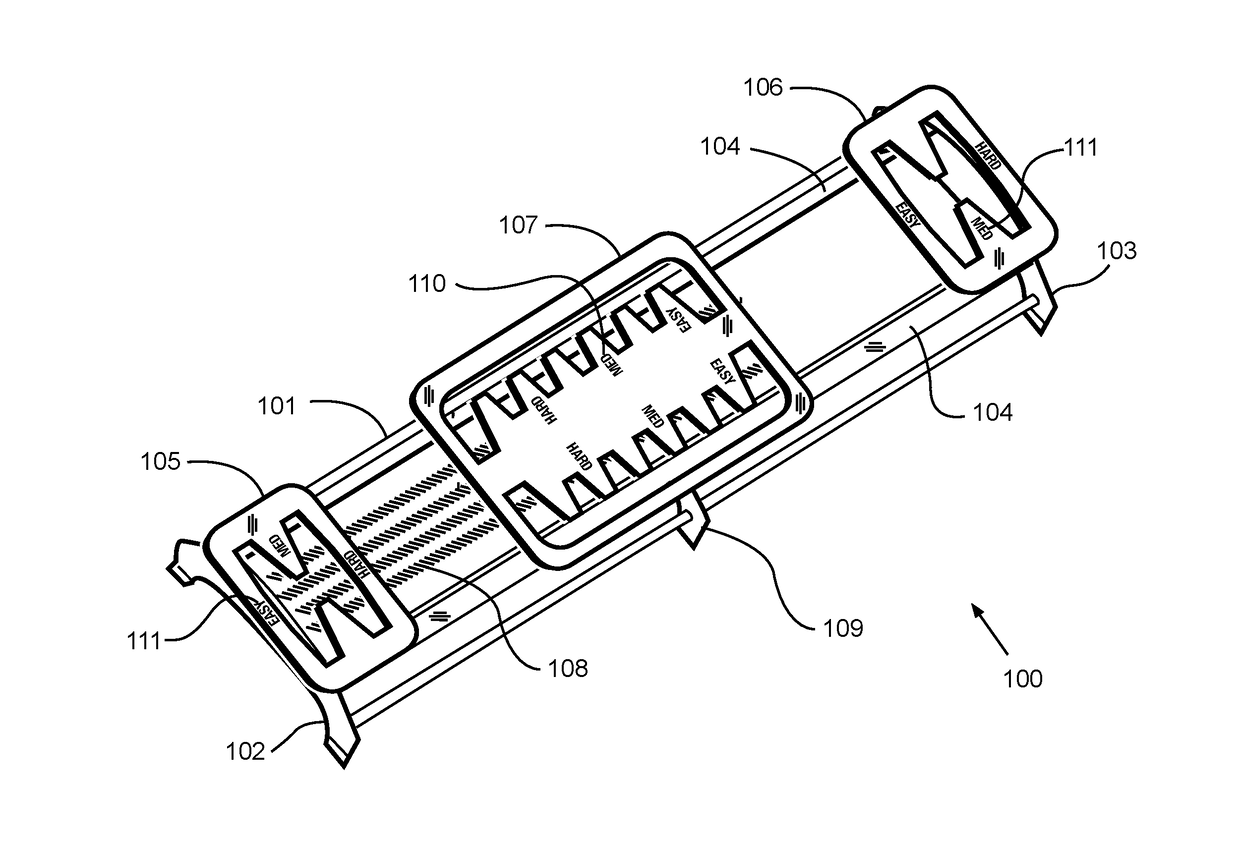
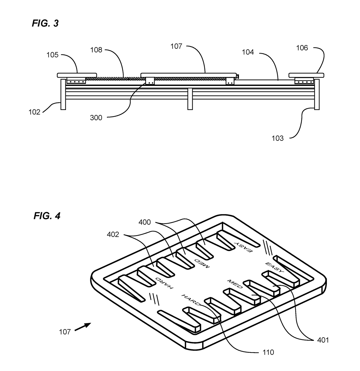
[0024]An example exercise machine resistance adjustment system generally comprises a frame, a carriage movably positioned on the frame, a spring connected to the carriage to apply a biasing force to the carriage, one or more left projections within the carriage adapted for a left hand of an exerciser to grasp, and one or more right projections within the carriage adapted for a right hand of an exerciser to grasp. The exerciser is able to efficiently adjust the amount of resistance force applied to the carriage by repositioning their hands (or feet) from a first set of projections at a first distance to a second set of projections at a second distance from the first end of the exercise machine.

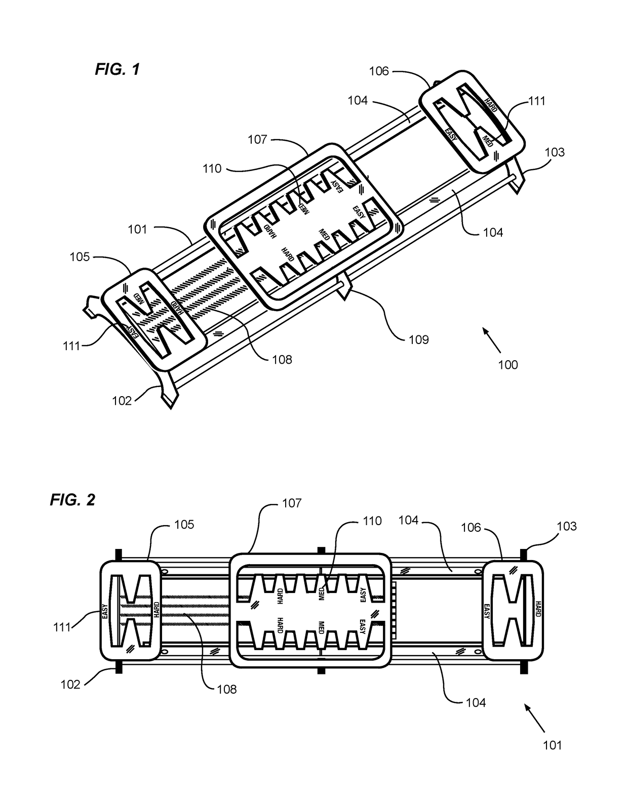
[0025]FIG. 1 is a perspective view of an exercise machine 100 in accordance with an example embodiment. A substantially longitudinal frame 101 is comprised of at least one rail (e.g. a pair of parallel rails 104) connected to vertical supports at a first end 102, and a second end 103. An inters...


PUM


Abstract

An exercise machine resistance adjustment system for providing an exerciser the ability to immediately adjust the resistance force by changing their body position on the movable carriage or end platforms. The exercise machine resistance adjustment system generally includes a frame, a carriage movably positioned on the frame, a spring connected to the carriage to apply a biasing force to the carriage, one or more left projections within the carriage adapted for a left hand of an exerciser to grasp, and one or more right projections within the carriage adapted for a right hand of an exerciser to grasp. The exerciser is able to efficiently adjust the amount of resistance force applied to the carriage by repositioning their hands (or feet) from a first set of projections at a first distance to a second set of projections at a second distance from the first end of the exercise machine.

Description

CROSS REFERENCE TO RELATED APPLICATIONS[0001]I hereby claim benefit under Title 35, United States Code, Section 119(e) of U.S. provisional patent application Ser. No. 62 / 281,899 filed Jan. 22, 2016 (Docket No. LAGR-009) and U.S. provisional patent application Ser. No. 62 / 438,542 filed Dec. 23, 2016 (Docket No. LAGR-088). The 62 / 281,899 application and 62 / 438,542 application are currently pending. The 62 / 281,899 application and 62 / 438,542 application are hereby incorporated by reference into this application.STATEMENT REGARDING FEDERALLY SPONSORED RESEARCH OR DEVELOPMENT[0002]Not applicable to this application.BACKGROUND[0003]Field[0004]Example embodiments in general relate to an exercise machine resistance adjustment system for providing an exerciser the ability to immediately adjust the resistance force by changing their body position on the movable carriage or end platforms.[0005]Related Art[0006]Any discussion of the related art throughout the specification should in no way be co...

Claims


Application Information

Patent Timeline
Patent Type & Authority Applications(United States)
IPC IPC(8): A63B21/00A63B23/12A63B22/00A63B23/04A63B21/02A63B21/04
CPCA63B21/00069A63B21/023A63B21/0428A63B23/12A63B22/0002A63B23/0405A63B21/4045A63B71/06A63B21/005A63B21/0083A63B21/0087A63B21/045A63B21/055A63B21/0552A63B22/0007A63B22/001A63B22/0089A63B22/203A63B2071/0694A63B21/00065A63B21/4034A63B21/4035
Inventor LAGREE, SEBASTIEN ANTHONY LOUIS
Owner LAGREE TECH INC
Why Eureka
Try Eureka