Driving machine

a driving machine and driving shaft technology, applied in the field of driving machines, can solve problems such as adverse effects, and achieve the effect of convenient use and convenient disassembly or assembly work

Active Publication Date: 2017-07-27
HITACHI KOKI CO LTD
View PDF39 Cites 16 Cited by
  • Summary
  • Abstract
  • Description
  • Claims
  • Application Information

AI Technical Summary

Benefits of technology

[0012]According to the invention, the driving switching mechanism is disposed on the trigger side. Thus, the configurations of the push lever mechanism, the push valve on the second switch side, and so on can be simplified to facilitate the disassembly or assembly work. Moreover, the driving switching mechanism is disposed on the trigger side, particularly, on the trigger lever. Therefore, the device main body can be made compact to achieve a driving machine that is easy to use. The aforementioned and other novel features of the invention can be understood through the description of the specification and the figures below.

Problems solved by technology

Therefore, it may have adverse effects when the driving machine is to be made smaller and lighter.

Method used


Image

  • Driving machine
  • Driving machine
  • Driving machine

Examples


first embodiment

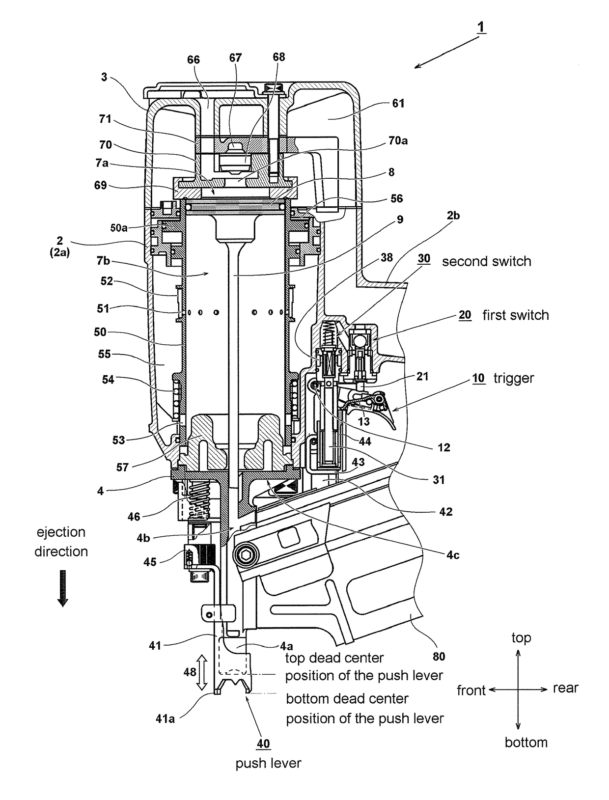
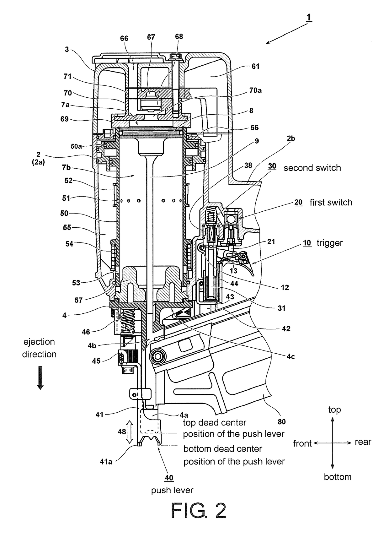
[0026]Hereinafter, embodiments of applying the invention to a nail driving machine that uses a compressed air system as the driving source are described with reference to the figures. In all the figures for illustration of the embodiments, members having the same function are assigned with the same reference numerals and the repeated descriptions will be omitted. Moreover, in the following embodiments, for convenience, the vertical and horizontal directions are defined as shown in the figures based on a state where the driving machine is disposed to make the direction in which the fastener is driven vertically downward. Nevertheless, the actual direction of driving nails may be the horizontal direction or other directions.

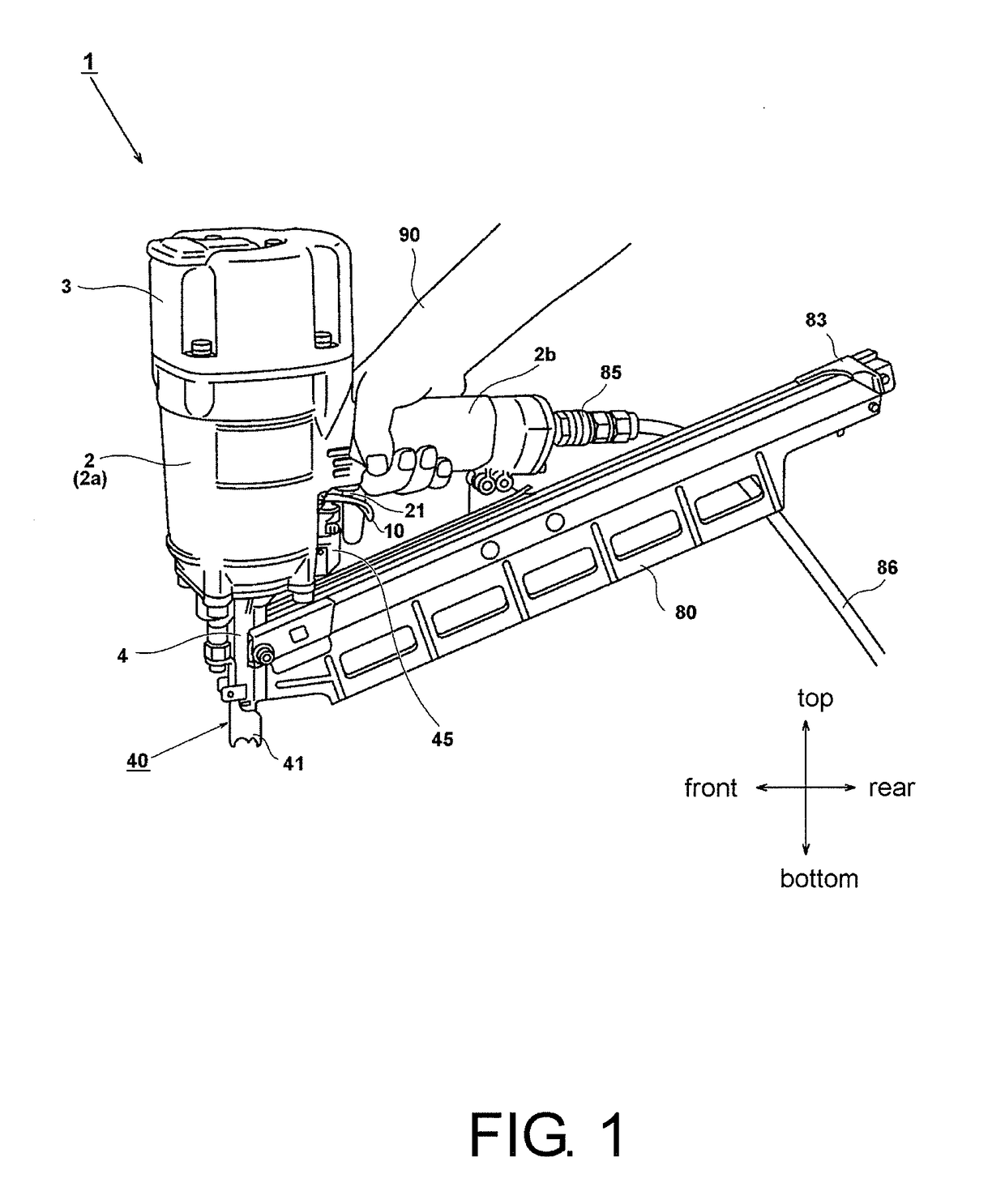
[0027]FIG. 1 is a perspective view showing the exterior of a driving machine 1 of this embodiment. In the driving machine 1, a nose member 4 for guiding nails to be driven to an ejection direction side is attached below a body part 2a of a housing 2. An outer case ...


PUM


Abstract

The disclosure discloses a driving machine includes a trigger, a first switch turned on or off by an operation of the trigger, a push lever that moves in response to an operation of pressing an ejection port of a fastener against a driven material, and a second switch turned on or off by movement of the push lever. The driving machine drives the fastener when the first switch and the second switch are both in the ON state. The trigger includes a switching mechanism to switch between a single-shot driving mode and a continuous-shot driving mode.

Description

CROSS-REFERENCE TO RELATED APPLICATION[0001]This application claims the priority benefit of Japan application serial no. 2016-012859, filed on Jan. 26, 2016. The entirety of the above-mentioned patent application is hereby incorporated by reference herein and made a part of this specification.BACKGROUND OF THE INVENTION[0002]Field of the Invention[0003]The invention relates to a driving machine that drives a fastener, such as a nail, by cooperative action of two switch mechanisms, which include a first switch operated by a trigger and a second switch operated by a push lever that moves in response to an operation of pressing a front end of an ejection port of the fastener against a driven material. In the driving machine, a driving switching mechanism for switching between a single-shot driving operation and a continuous-shot driving operation is mounted to the trigger portion.[0004]Description of Related Art[0005]The commonly-known portable driving machine sequentially drives out f...

Claims


Application Information

Patent Timeline
Patent Type & Authority Applications(United States)
IPC IPC(8): B25C1/00B25C1/04
CPCB25C1/043B25C1/008
Inventor IIJIMA, YOSHIMITSUKITAGAWA, HIROKI
Owner HITACHI KOKI CO LTD
Why Eureka
Try Eureka