
Interlocking gladhands

Active Publication Date: 2017-07-27
NEW YORK AIR BRAKE CORP
View PDF1 Cites 0 Cited by
  • Summary
  • Abstract
  • Description
  • Claims
  • Application Information

AI Technical Summary

Benefits of technology

The patent describes a unique coupling mechanism that allows two parts to be connected and disconnected without needing special locking mechanisms or excessive force. The coupling mechanism uses a resilient gasket and ridge and groove design to keep the parts in engagement during normal use. The parts are designed to automatically disconnect if too much force is applied, preventing premature disconnection. This design reduces the need for expensive and complicated locking mechanisms.

Problems solved by technology

This approach has proven to be unreliable in the field, however, as it is easily disconnected by involuntary forces, such as hose vibration.
While the art includes locking mechanisms for gladhands, these approaches have not been adopted in the field because they require that the gladhand be unlocked through additional steps or manipulation that are not practical for current methods of rail car separation or compliant with the applicable industry regulations and standards, such as those promulgated by the Association of American Railroads (AAR).

Method used


Image

  • Interlocking gladhands
  • Interlocking gladhands
  • Interlocking gladhands

Examples


Embodiment Construction

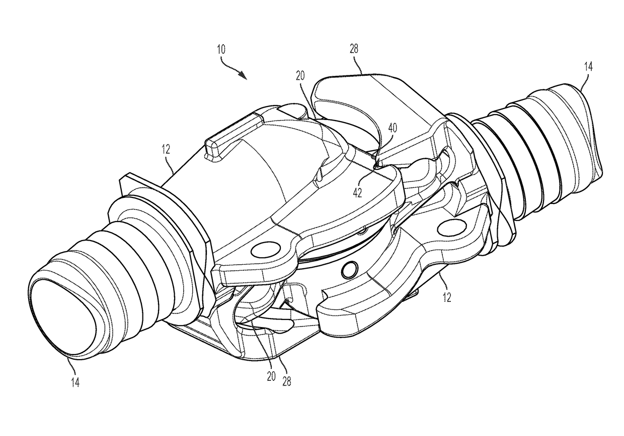
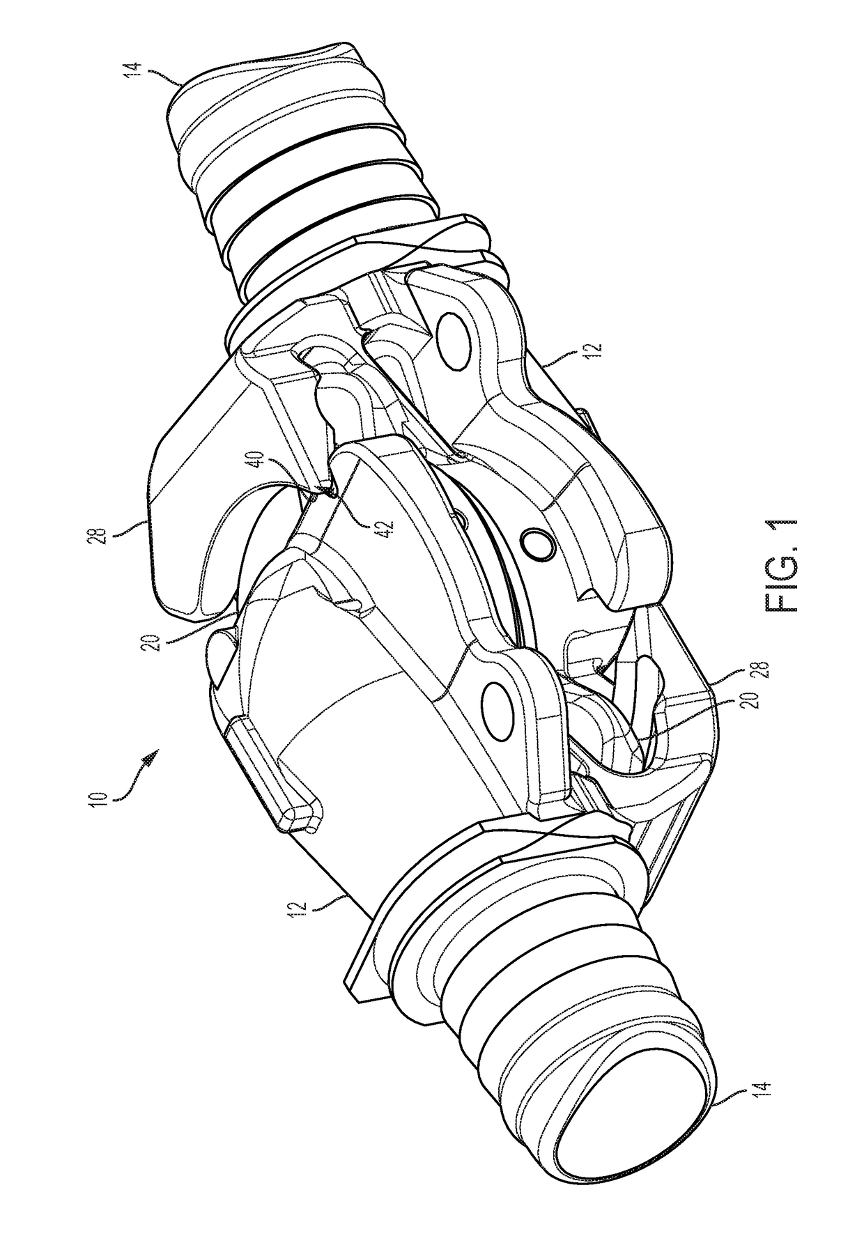
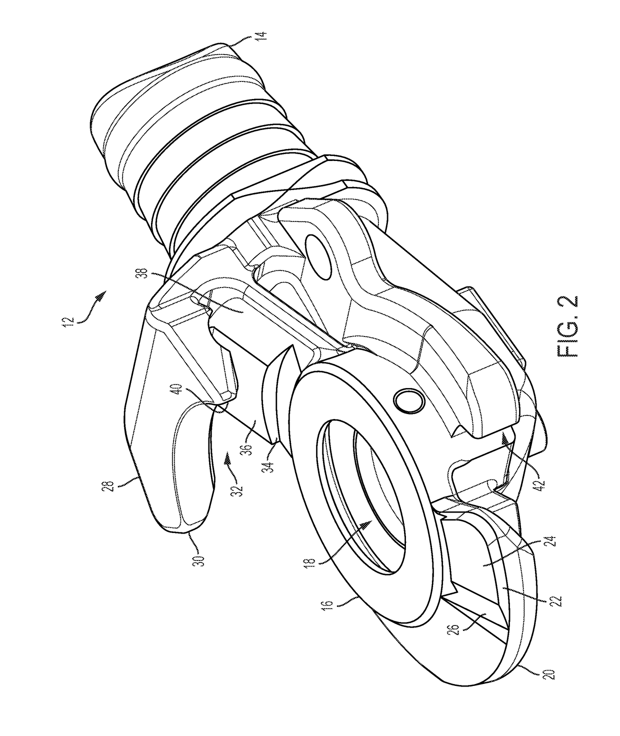
[0015]Referring now to the drawings, wherein like reference numerals refer to like parts throughout, there is seen in FIGS. 1 through 5, a gladhand coupling 10 comprising a pair of coupling halves 12 that may be rotatable coupled together. Each coupling half 12 includes an air hose shank 14 for the connecting an air hose (not shown) to coupling half 12. Referring to FIGS. 2 and 3, coupling half 12 is hollow and includes face 16 extending along a plane and having an opening 18 formed therethrough to define an air passage that is in fluid communication with the interior of connector 14 and thus the internal diameter of an air hose attached thereto. As with conventional gladhands, coupling 10 is connected and disconnected by rotating one coupling half 12 relative to another coupling half 12, thereby connecting and disconnecting the air hoses coupled to the shanks 14 of each coupling half 12. All of the elements of gladhand coupling 10 may be formed via metal casting when manufacturing ...


PUM


Abstract

A gladhand coupling that prevents inadvertent separation of the coupling halves without the need for additional structure or manipulation to connect and disconnect the halves. Each half is equipped with a lug having a ramped pad and a flange defining a channel having a corresponding ramped pad. When two halves are positioned together then rotated into the locked position, the ramped pad of the lug is positioned proximately to the ramped pad of the flange to prevent inadvertent lateral compression of the two halves that could cause unintentional uncoupling. The coupling may be disconnected by simple rotation of one coupling half relative to the other and by pulling the coupling apart as done by current rail car decoupling procedures without the need for manual manipulation of extraneous locking mechanisms.

Description

BACKGROUND OF THE INVENTION[0001]1. Field of the Invention[0002]The present invention relates to air brake hose connectors and, more particularly, to a connector having a mechanical interlock to prevent inadvertent decoupling.[0003]2. Description of the Related Art[0004]Air brake hose couplers, typically referred to as gladhand connectors, have two interlocking members fitted to the hoses that supply pressurized air from a locomotive to the railway air brakes of the railroad cars of a train and then coupled together to join the hoses together. Conventional gladhands used throughout in the rail industry do not include any mechanism that locks the gladhands together when in the coupled position. Instead, the prevailing gladhand design uses the compression of a rubber gasket between the faces of the two gladhands as the sole means to hold a rib in a groove, thus holding the gladhands together. This approach has proven to be unreliable in the field, however, as it is easily disconnected...

Claims


Application Information

Patent Timeline
IPC IPC(8): B61G5/08
CPCB61G5/08
Inventor AIKEN, JEFFREYESTELLE, TAYLOR
Owner NEW YORK AIR BRAKE CORP
Learn More