
Electric Submersible Pump with Ultrasound for Solid Buildup Removal

a submersible pump and ultrasonic technology, applied in the direction of fluid removal, non-positive displacement fluid engines, borehole/well accessories, etc., can solve the problems of increasing esp trips, motor electrical shorts, motors to work harder and exceed the design rating, etc., to prevent, remove or at least reduce solid buildup, prolong the esp run life, and increase hydrocarbon production

Active Publication Date: 2017-07-27
SAUDI ARABIAN OIL CO
View PDF3 Cites 3 Cited by
  • Summary
  • Abstract
  • Description
  • Claims
  • Application Information

AI Technical Summary

Benefits of technology

The patent describes a system that uses ultrasonic technology to prevent and remove buildup in an electric submersible pump system. This helps to prolong the lifespan of the pump and increase the amount of oil produced. The ultrasonic technology can also be used to clear blockages in alternative flow paths.

Problems solved by technology

A challenge with ESP operations is solid precipitation and deposition on the ESP string, including on the motor housing, pump intake, pump stages such as impellers and diffusers, and pump discharge.
Deposition of solids can result in an increase in ESP trips due to motor high temperature and overload.
Motor electrical shorts can occur due to scale and corrosion buildup in the pump forcing the motor to work harder and exceed its designed rating.
Moreover, as adequate flow of produced fluid past the motor is required for cooling, solids blockage of a pump's flow path and solids build up around the outside of the motor leads to rapid motor internal heat rise, insulation breakdown and electrical short.
Some ESP wells cannot restart after a shutdown due to shaft rotation restriction from solids build up between the shaft and radial bearings, therefor requiring a workover to change out the ESP.
Continuous chemical injection is often utilized to treat CaCo3 scale in order to increase ESP reliability and run life, but retrofitting existing ESP wells with such a system requires high capital expenditures and an increase in operating expenses, plus the introduction of new safety concerns to unmanned platforms.

Method used


Image

  • Electric Submersible Pump with Ultrasound for Solid Buildup Removal
  • Electric Submersible Pump with Ultrasound for Solid Buildup Removal
  • Electric Submersible Pump with Ultrasound for Solid Buildup Removal

Examples


Embodiment Construction

[0017]Embodiments of the present disclosure will now be described more fully hereinafter with reference to the accompanying drawings which illustrate embodiments of the disclosure. Systems and methods of this disclosure may, however, be embodied in many different forms and should not be construed as limited to the illustrated embodiments set forth herein. Rather, these embodiments are provided so that this disclosure will be thorough and complete, and will fully convey the scope of the disclosure to those skilled in the art. Like numbers refer to like elements throughout, and the prime notation, if used, indicates similar elements in alternative embodiments or positions.

[0018]In the following discussion, numerous specific details are set forth to provide a thorough understanding of the present disclosure. However, it will be obvious to those skilled in the art that embodiments of the present disclosure can be practiced without such specific details. Additionally, for the most part, ...


PUM


Abstract

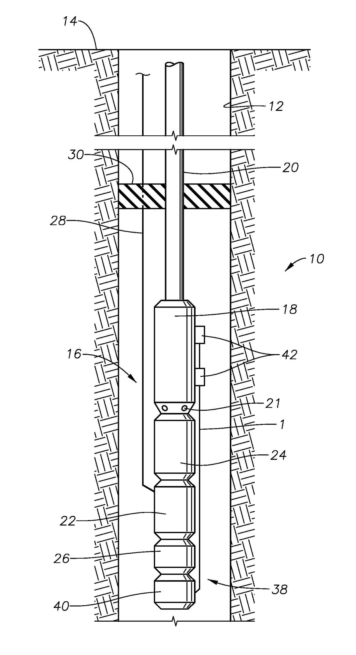
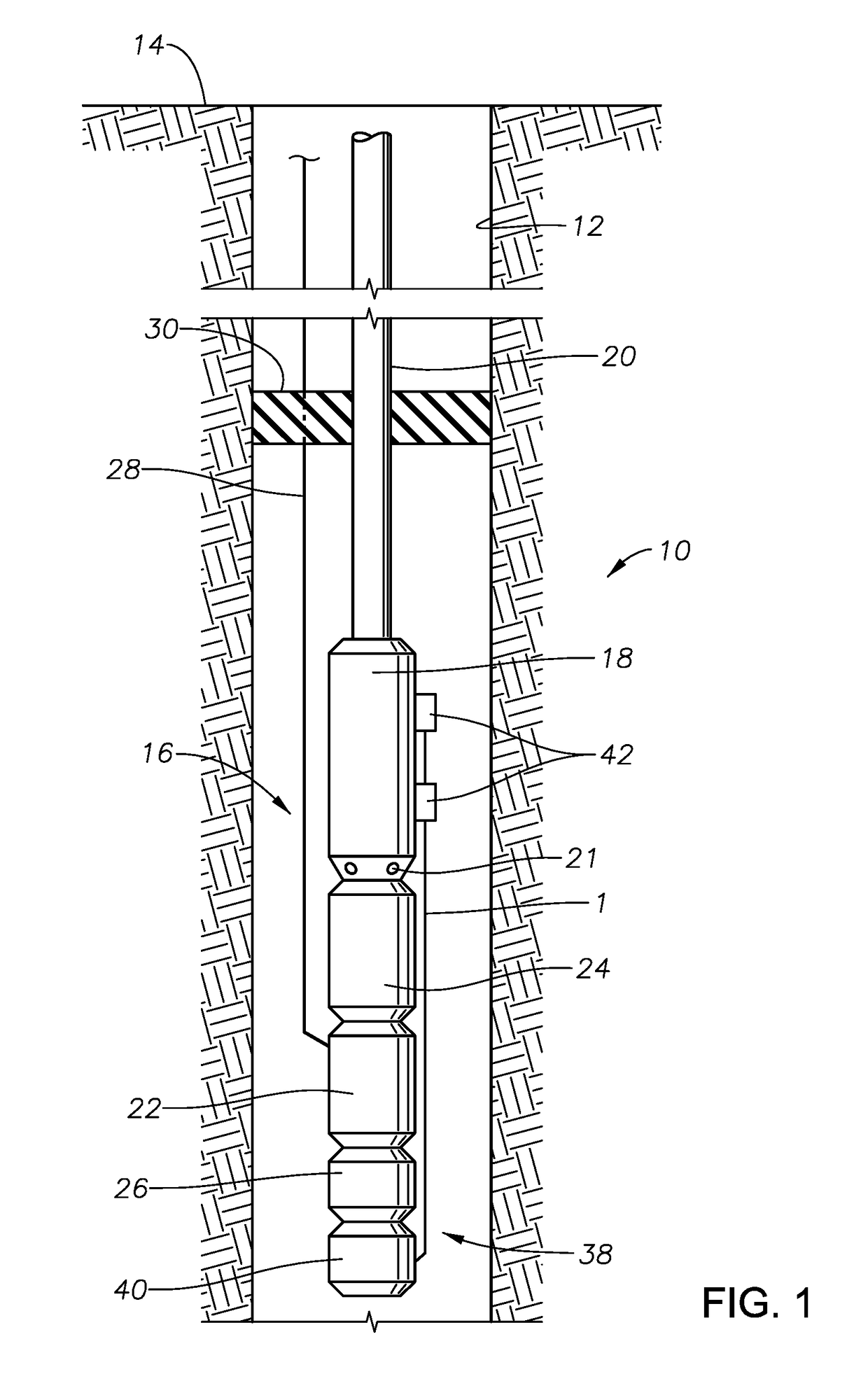
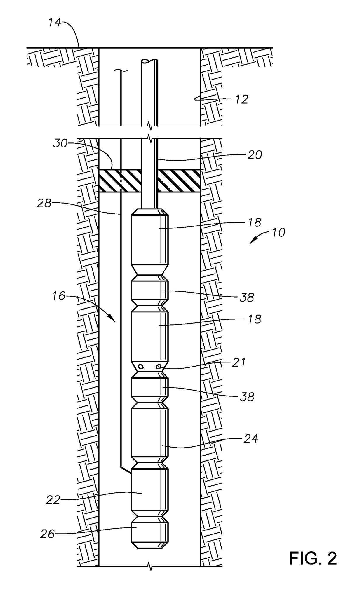
A system for providing artificial lift to wellbore fluids having solid buildup removal capabilities includes a pump submerged in wellbore fluids and in fluid communication with a tubular member extending within a wellbore. The pump is oriented to selectively boost a pressure of the wellbore fluids traveling from the wellbore towards an earth's surface. A motor is located within the wellbore providing power to the pump. A seal assembly has a first side connected to the motor and a second side connected to the pump, wherein the pump, the motor and the seal assembly together form a submersible pump string. An ultrasonic device is connected to the submersible pump string and operable to produce pressure waves.

Description

BACKGROUND OF THE DISCLOSURE[0001]1. Field of the Disclosure[0002]The present disclosure relates to electrical submersible pumps used in hydrocarbon development operations, and more specifically, the disclosure relates to electrical submersible pumps with ultrasonic cleaning capability.[0003]2. Description of the Related Art[0004]In hydrocarbon developments, it is common practice to use electric submersible pumping systems (ESPs) as a primary form of artificial lift. A challenge with ESP operations is solid precipitation and deposition on the ESP string, including on the motor housing, pump intake, pump stages such as impellers and diffusers, and pump discharge. Solid compositions can include one or more types of scales, such as CaCO3, CaSO4, SrSO4 CaMg(CO3)2, and corrosion products. Deposition of solids can result in an increase in ESP trips due to motor high temperature and overload. Motor electrical shorts can occur due to scale and corrosion buildup in the pump forcing the motor...

Claims


Application Information

Patent Timeline
Patent Type & Authority Applications(United States)
IPC IPC(8): E21B43/12
CPCE21B43/128F04D13/10
Inventor XIAO, JINJIANGLASTRA, RAFAEL ADOLFOSHEPLER, RANDALL
Owner SAUDI ARABIAN OIL CO
Learn More