Damping device of window covering

a technology of adamant device and a window covering, which is applied in the direction of door/window protection device, mechanical apparatus, shock absorber, etc., can solve the problems of component wear, and excessive speed of the covering material

Active Publication Date: 2017-07-27
NIEN MADE ENTERPRISE CO LTD
View PDF28 Cites 11 Cited by
  • Summary
  • Abstract
  • Description
  • Claims
  • Application Information

AI Technical Summary

Benefits of technology

[0006]In view of the above, the primary objective of the present invention is to provide a damping device of a window covering, which provides a desired damping effect at different temperature or after a long period use.
[0021]Whereby, with the interaction between the magnetic member and the metal member, the damping device provides a desired damping effect at different temperature or after a long period use, such that the rotation of the metal member is slow down, which slows down the movement of the covering material.

Problems solved by technology

During the process of extending the covering material, the weight of the covering material would generate a downward pulling force, which accelerates the rolling of the rotary shaft, and makes the covering material extend with an excessive speed.
As a result, some components may be worn, or the covering material may bump into objects below.
Similarly, during the process of raising the covering material, an excessive rolling speed of the rotary shaft would make the covering material raise too fast as well.
However, the viscosity of the oil in the oil damping device is sensitive to temperature.
When the temperature is high, the viscosity of the oil is low, which reduces the damping effect; in contrast, when the temperature is low, the viscosity of the oil is high, which affects the smoothness of operating the window covering.
Also, after being used for a long period, the oil may leak from the oil damping device, which worsens the damping effect, and even makes the oil damping device completely unable to provide the damping effect.

Method used


Image

  • Damping device of window covering
  • Damping device of window covering
  • Damping device of window covering

Examples


Embodiment Construction

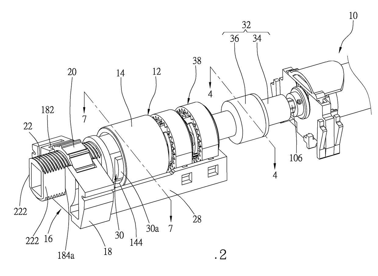
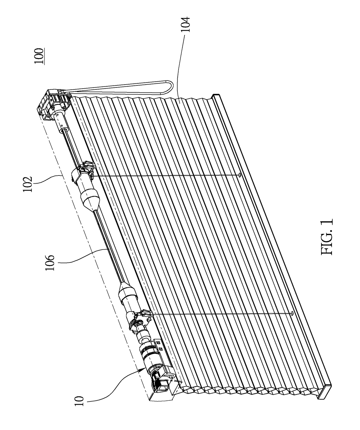
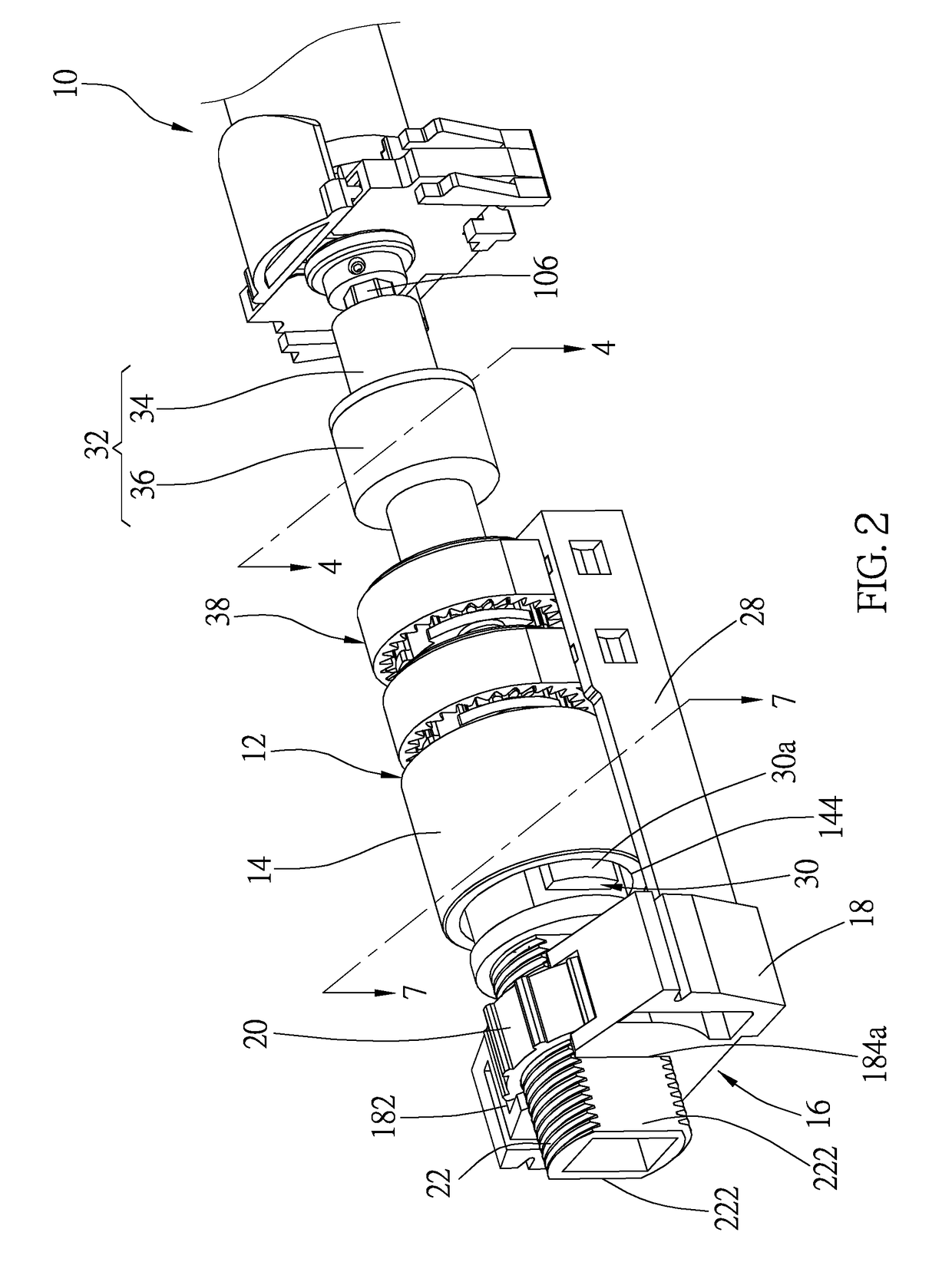
[0033]As shown in FIG. 1, a window covering 100 provided with a damping device 10 includes a headrail 102, a covering material 104, and a driving device which is a rotary shaft 106 in the first preferred embodiment, wherein the rotary shaft 106 is located in the headrail 102 to raise and extend the covering material 104. The damping device 10 is provided in the headrail 102, and is connected to the rotary shaft 106. As illustrated in FIG. 2 to FIG. 6, the damping device 10 includes a metal member 12, a magnetic member which is a magnet 30 in the first preferred embodiment, and an adjusting unit 16, a one-way clutch 32, and a gearbox 38.

[0034]As depicted in FIG. 2 to FIG. 4, the metal member 12 of the damping device 10 includes a metal roller 14 and a bushing 15. The metal roller 14 in the first preferred embodiment is made of nonmagnetic metal, such as aluminum and copper, and has a closed end 142 and an open end 144 opposite to each other. The bushing 15 is provided in the metal ro...


PUM

PropertyMeasurementUnit
magnetic poleaaaaaaaaaa
magnetic fieldaaaaaaaaaa
magneticaaaaaaaaaa

Abstract

A damping device of a window covering is provided, including a headrail, a covering material, and a driving device, wherein the driving device is located in the headrail to raise and extend the covering material. The damping device is provided in the headrail, and includes a metal member and a magnetic member, wherein at least a magnetic pole of the magnetic member faces the metal member. The metal member is located within a magnetic field of the magnetic member. Either one or both the metal member and the magnetic member is drivable by the driving device to make the metal member and the magnetic member move relative to each other. Whereby, the damping device is able to provide a desired damping effect at different temperature or after a long period use, such that the rotation of the metal member and the movement of the covering material are slowed down.

Description

BACKGROUND OF THE INVENTION[0001]1. Technical Field[0002]The present invention relates generally to a reeling mechanism of a window covering, and more particularly to a damping device which is capable of slowing down the speed of raising and extending the window covering.[0003]2. Description of Related Art[0004]A conventional window covering includes a headrail, a covering material, and a rotary shaft, wherein the rotary shaft is provided in the headrail to raise and extend the covering material. During the process of extending the covering material, the weight of the covering material would generate a downward pulling force, which accelerates the rolling of the rotary shaft, and makes the covering material extend with an excessive speed. As a result, some components may be worn, or the covering material may bump into objects below. Similarly, during the process of raising the covering material, an excessive rolling speed of the rotary shaft would make the covering material raise to...

Claims


Application Information

Patent Timeline
Patent Type & Authority Applications(United States)
IPC IPC(8): F16F15/18E06B9/322
CPCF16F15/18F16F2222/06E06B9/322E06B9/388E06B2009/807E06B9/80B65H75/486E06B9/307E06B2009/3222E06B9/324F16F9/125F16F2222/04F16F2222/12F16F2224/025F16F2224/045
Inventor CHEN, LINNIEN, KENG-HAO
Owner NIEN MADE ENTERPRISE CO LTD
Why Eureka
Try Eureka