
Vascular channel manufacture by deflagration

a technology of vascular channel and manufacture, which is applied in the field of vascular channel manufacture by deflagration, can solve the problems of difficult consistent removal of previously used sacrificial materials, difficult deposition of vaporization and melting removal methods, and difficult deposition of sacrificial materials, etc., and achieves the effects of rapid deflagration process, difficult and slow manufacturing of vascular channel in composite materials, and removal of sacrificial materials

Active Publication Date: 2020-08-18
GM GLOBAL TECH OPERATIONS LLC
View PDF13 Cites 1 Cited by
  • Summary
  • Abstract
  • Description
  • Claims
  • Application Information

AI Technical Summary

Benefits of technology

The patent describes a method for making vascular channels in composite materials. Previous methods used sacrificial materials that were difficult to remove consistently, and methods that involved melting or vaporizing the materials can slow down the process and leave residual material in the channels. The new method uses deflagration, which is a rapid and efficient process. The heat generated during deflagration is quickly dissipated, minimizing damage to the composite material. The technical effect is a faster and more reliable process for making vascular channels in composite materials.

Problems solved by technology

Vascular channel manufacturing in composite materials is often challenging and slow.
Previously used sacrificial materials were difficult to remove consistently.
However, vaporization (i.e., thermal depolymerization) and melting removal methods can be slow and tend to leave residual material in the channels.

Method used


Image

  • Vascular channel manufacture by deflagration
  • Vascular channel manufacture by deflagration
  • Vascular channel manufacture by deflagration

Examples


Embodiment Construction

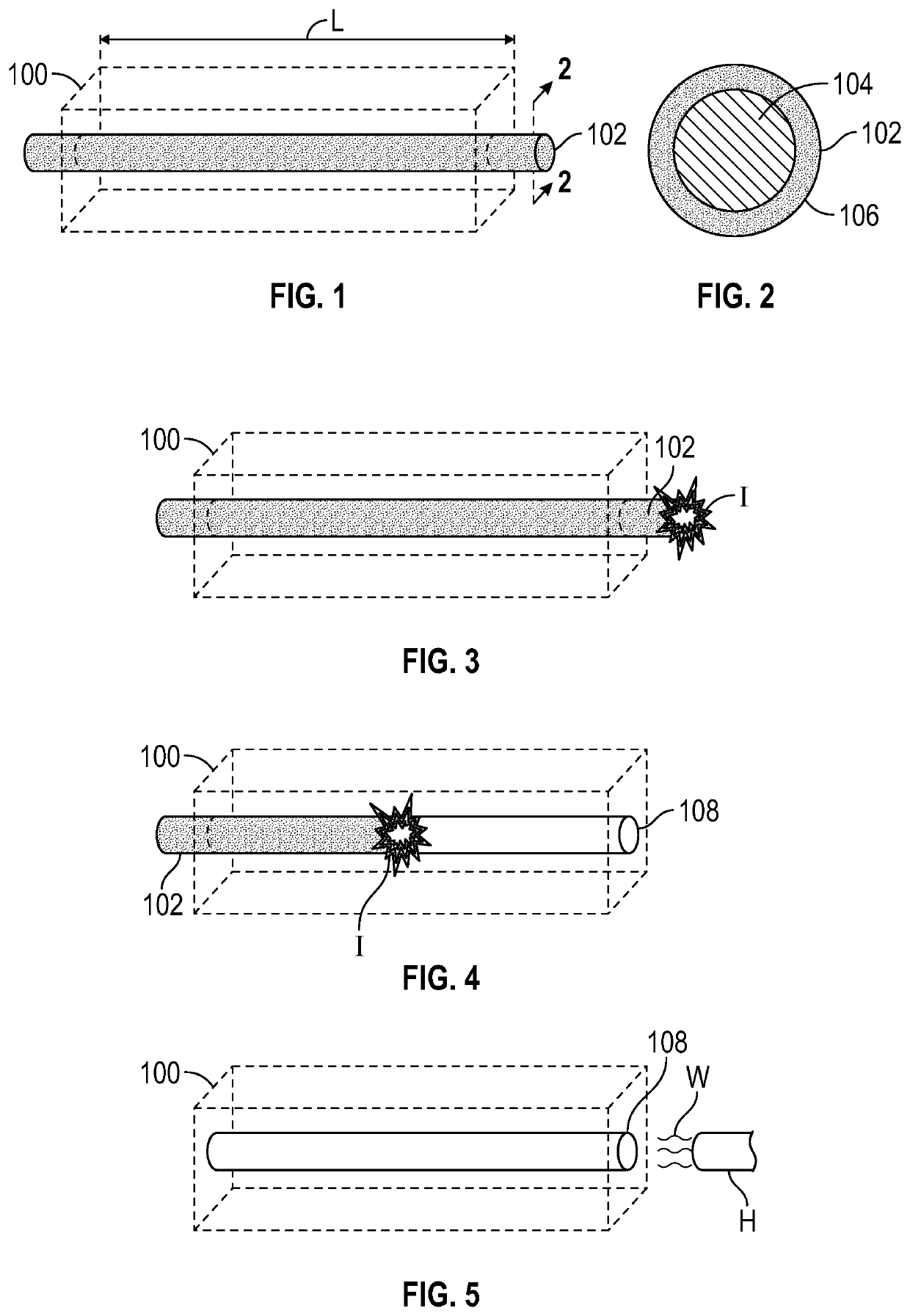
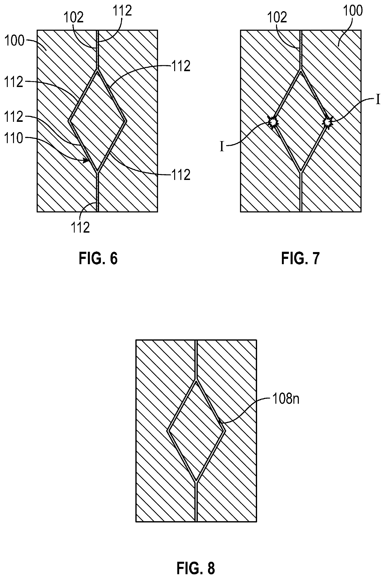
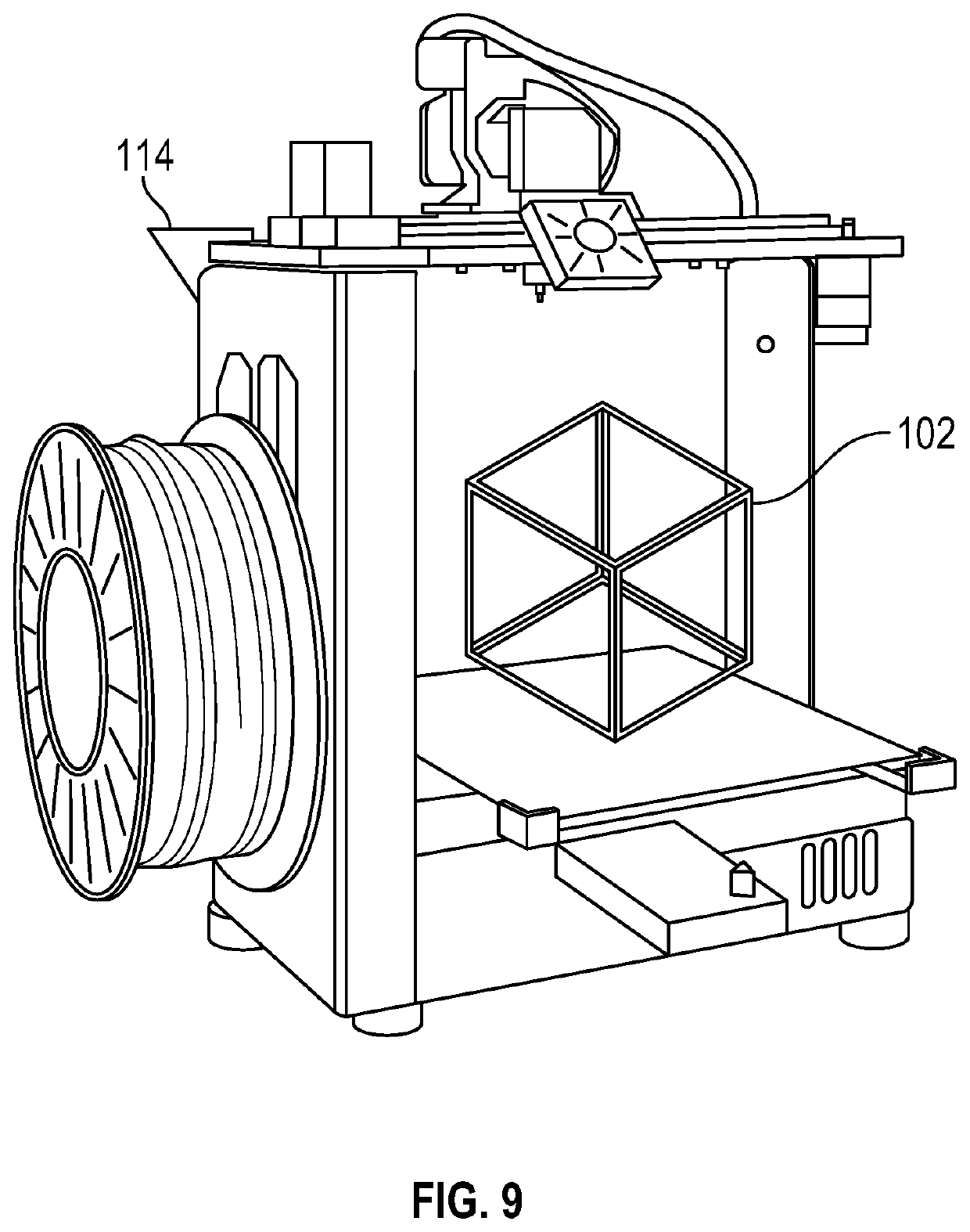
[0025]With reference to FIG. 1, the present disclosure describes a method of forming channels within a substrate 100 using deflagration of a sacrificial material. The substrate 100 may be wholly or partly made of a polymer or a polymer composite. In this method, a sacrificial component 102 is molded directly into the substrate 100 as shown in FIG. 1. For example, the sacrificial component 102 is molded directly to the substrate 100 such that the sacrificial component 102 is at least partially disposed inside the substrate 100. For instance, after molding, a majority of the sacrificial component 102 may be entirely disposed inside the substrate 100 to facilitate the formation of thru-holes. However, at least part of the sacrificial component 102 should be disposed outside of the substrate 100 to allow it to be ignited as discussed below.

[0026]With specific reference to FIG. 2, the sacrificial component 102 includes a combustible core 104 and a protective shell 106 surrounding the com...


PUM

PropertyMeasurementUnit
temperatureaaaaaaaaaa
flash pointaaaaaaaaaa
densityaaaaaaaaaa

Abstract

A method of forming channels within a substrate includes: (a) molding a sacrificial component directly into the substrate; (b) igniting the sacrificial component to cause a deflagration of the sacrificial component, thereby forming a channel in the substrate; and (c) cleaning the channel in the substrate to remove byproducts of the deflagration of the sacrificial component. The sacrificial component includes a combustible material with a protective shell, and the substrate includes a polymeric material.

Description

INTRODUCTION[0001]The present disclosure relates to vascular channel manufacture by deflagration. For instance, the presently disclosed method can be used for forming channels within polymers, metals, or composites using deflagration of a sacrificial material.SUMMARY[0002]Vascular channel manufacturing in composite materials is often challenging and slow. Previously used sacrificial materials were difficult to remove consistently. For example, the melting and / or vaporizing has been used to remove sacrificial material. However, vaporization (i.e., thermal depolymerization) and melting removal methods can be slow and tend to leave residual material in the channels. Residual materials in turn restrict fluid flow. Deflagration is a rapid process and material left behind is easily removed. Also, the deflagration process described herein does not require the entire composite to be heated, unlike melting and vaporization. Heat generated through deflagration is rapidly dissipated to minimiz...

Claims


Application Information

Patent Timeline
Patent Type & Authority Patents(United States)
IPC IPC(8): B29C33/44B33Y40/00B22D29/00B29C45/44B29C64/30B22D19/00B29D22/00B29C67/00B29C71/02B33Y10/00B29L31/34
CPCB29C64/30B29C45/4457B29C33/448B22D29/003B33Y40/00B22D19/0072B29D22/00B29C71/02B29L2031/34B22D29/007B33Y10/00B29C67/0033B33Y80/00B33Y40/20
Inventor ELLISON, NICOLECOPPOLA, ANTHONY M.
Owner GM GLOBAL TECH OPERATIONS LLC
Learn More