Retaining structure for honeycomb structure and marine propulsion device

Active Publication Date: 2012-08-02
YAMAHA MOTOR CO LTD
View PDF9 Cites 0 Cited by
  • Summary
  • Abstract
  • Description
  • Claims
  • Application Information

AI Technical Summary

Benefits of technology

[0009]Preferred embodiments of the present invention provide a retaining structure for a honeycomb structure and a marine propulsion device which are lightweight and adapted to minimize thermal effects on surrounding components.
[0012]In a retaining structure for a honeycomb structure according to a preferred embodiment of the present invention, having the honeycomb structure made of a ceramic material enables weight to be reduced to a greater extent than with a component made of metal such as stainless steel. Moreover, the housing directly retains the retainer mat and the honeycomb structure. Because of this, further reduction in weight is possible than with the case where the housing retains the retainer mat and the honeycomb structure via an additional member. Moreover, because the housing is made of aluminum and stainless steel is not used, weight can be reduced even further. Moreover, the coolant passage is arranged to extend from one end of the housing to the other. Because of this, erosion of the housing can be prevented. Moreover, thermal effects on components surrounding the retaining structure for the honeycomb structure can be minimized.
[0013]In a marine propulsion device according to another preferred embodiment of the present invention, because the honeycomb structure is made of a ceramic material, weight can be reduced to a greater extent than with a component made of metal such as stainless steel. Moreover, the housing directly retains the retainer mat and the honeycomb structure. Because of this, the weight can be reduced to a greater extent than with the case where the housing retains the retainer mat and the honeycomb structure via an additional member. Moreover, because the housing is made of aluminum and stainless steel is not used, weight can be reduced even further. Moreover, the coolant passage is arranged to extend from one end of the housing to the other. Because of this, erosion of the housing can be prevented. Moreover, thermal effects on components surrounding the retaining structure for the honeycomb structure can be minimized.

Problems solved by technology

Consequently, the housing which retains the honeycomb structure reaches a high temperature as a result of being directly affected by heat emanating from the honeycomb structure.
However, because stainless steel is heavy, stainless steel housings are not appropriate for engines that are required to be lighter in weight.
Also, because the housing itself becomes extremely hot, there is a possibility of surrounding constituent components being thermally affected thereby.
For example, in an outboard motor, a lighter weight of the engine is required due to the fact that the weight of the engine significantly affects the performance of the boat.
Because of this, if the honeycomb structure is disposed close to the engine, there is a possibility of heat from the housing containing the honeycomb structure adversely affecting the other constituent components.

Method used


Image

  • Retaining structure for honeycomb structure and marine propulsion device
  • Retaining structure for honeycomb structure and marine propulsion device
  • Retaining structure for honeycomb structure and marine propulsion device

Examples


Embodiment Construction

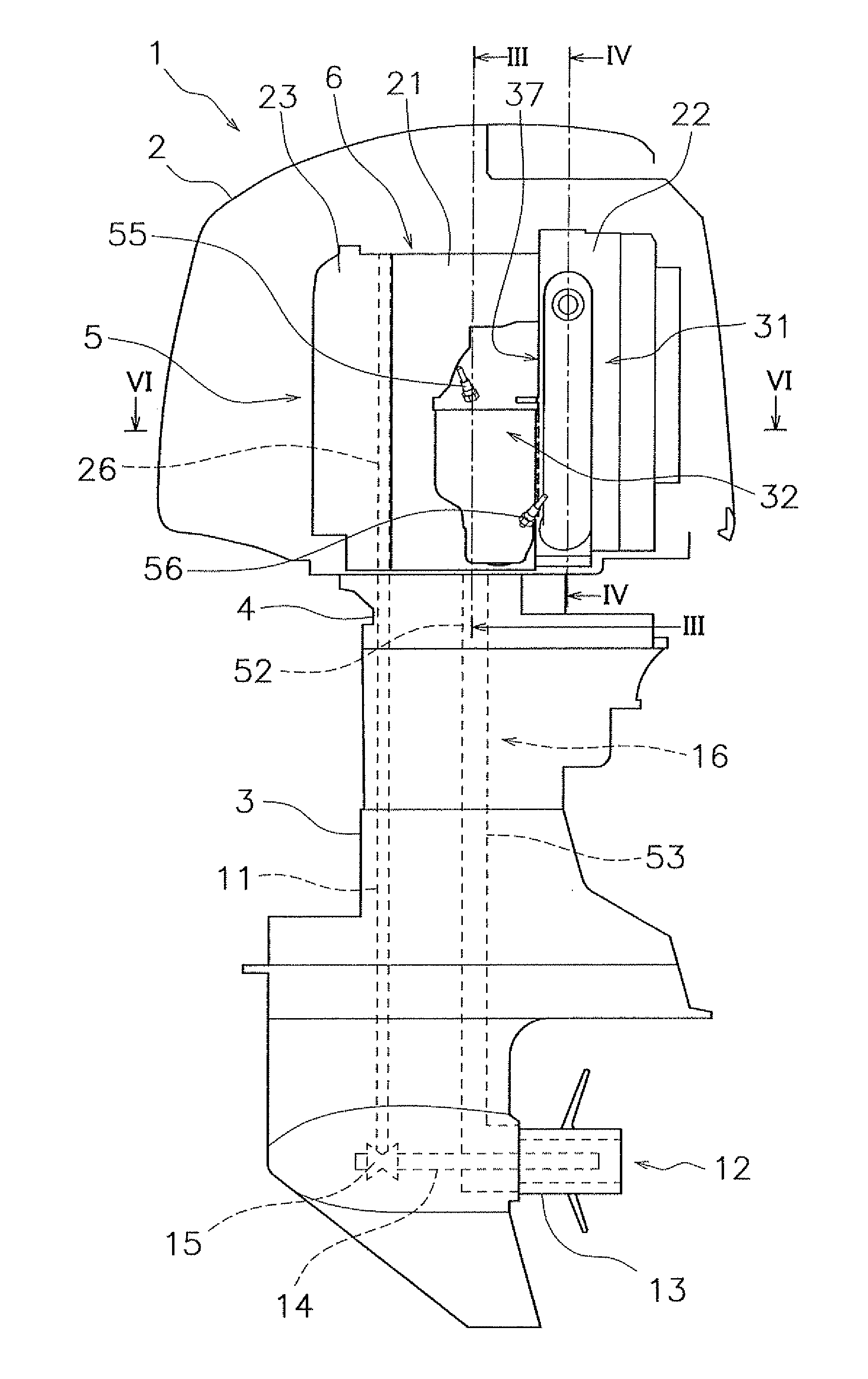
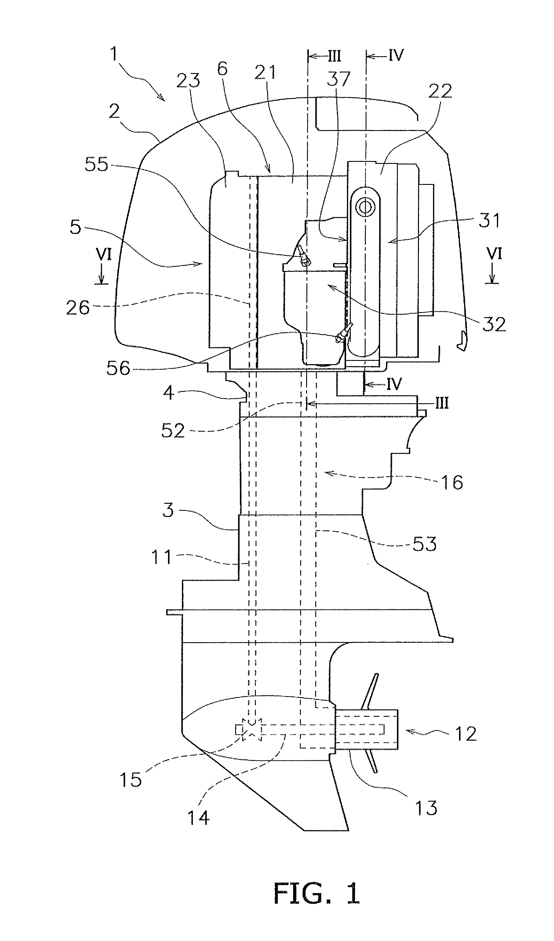
[0022]FIG. 1 is a side view depicting an outboard motor 1 according to a preferred embodiment of the present invention.

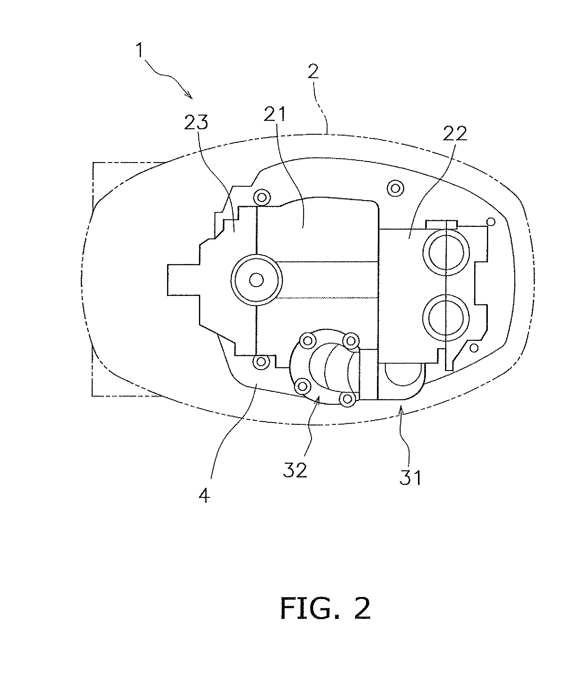
[0023]FIG. 2 is a top view of the outboard motor 1. As shown in FIGS. 1 and 2, the outboard motor 1 according to the present preferred embodiment includes an upper casing 2, a lower casing 3, an exhaust guide portion 4, and an engine unit 5. For ease of understanding, the upper casing 2 is shown in cross section in FIG. 1. In FIG. 2, the outer contours of the upper casing 2 are shown by double-dot and dash lines. The upper casing 2, the lower casing 3, and the engine unit 5 are fixed to the exhaust guide portion 4.

[0024]The engine unit 5 is disposed inside the upper casing 2. The engine unit 5 includes an engine 6, an exhaust manifold 31, and a catalytic converter 32. A drive shaft 11 is disposed inside the lower casing 3. The drive shaft 11 is disposed along the vertical direction inside the lower casing 3. The drive shaft 11 is fixed to a crankshaft 26 of the engi...


PUM

PropertyMeasurementUnit
Structureaaaaaaaaaa

Abstract

A retaining structure for a honeycomb structure includes a honeycomb structure, a retainer mat, and a housing. The honeycomb structure is a member made of a ceramic material. The retainer mat is in contact with the honeycomb structure and directly retains the honeycomb structure. The housing is in contact with the retainer mat and directly retains the retainer mat. The housing is made of aluminum. The housing includes an inner wall, an outer wall, and a coolant passage. The inner wall is in contact with the retainer mat. The coolant passage is located between the inner wall and the outer wall. An inflow port of the coolant passage is located at one end of the housing. A discharge port of the coolant passage is located at the other end of the housing.

Description

BACKGROUND OF THE INVENTION[0001]1. Field of the Invention[0002]The present invention relates to a retaining structure for a honeycomb structure, and to a marine propulsion device.[0003]2. Description of the Related Art[0004]Installation of a honeycomb structure in the exhaust device of an engine is known in the prior art. For example, a catalytic converter disclosed in Japanese Laid-open Patent Application No. 2007-100608 has a catalyst support, a retainer mat, and a housing. The catalyst support is composed of a honeycomb structure. The housing is formed of a thin sheet material, and directly retains the honeycomb structure which is wrapped in the retainer mat. The housing is welded to an exhaust manifold, and constitutes an exhaust passage.[0005]Because the honeycomb structure is disposed midway along the exhaust passage, it is exposed to high-temperature exhaust gas. Consequently, the housing which retains the honeycomb structure reaches a high temperature as a result of being d...

Claims


Application Information

Patent Timeline
IPC IPC(8): B63H21/38B63H21/32B63H21/36B01J19/00
CPCB01D46/2418Y10T29/49879B01D46/42B63H21/32
Inventor NAKAYAMA, KOICHISUZUKI, TOSHIOOCHIAI, KATSUMI
Owner YAMAHA MOTOR CO LTD
Why Eureka
Try Eureka