
Retaining structure for honeycomb structure and marine propulsion device
a technology of honeycomb structure and retaining structure, which is applied in the direction of marine propulsion, vessel construction, separation processes, etc., can solve the problems of thermal impact on surrounding constituent components, inadequacies of stainless steel housings, and high temperature of the honeycomb structure, so as to reduce weight, reduce weight, the effect of reducing the weigh
- Summary
- Abstract
- Description
- Claims
- Application Information
AI Technical Summary
Benefits of technology
Problems solved by technology
Method used
Image

Examples
Embodiment Construction
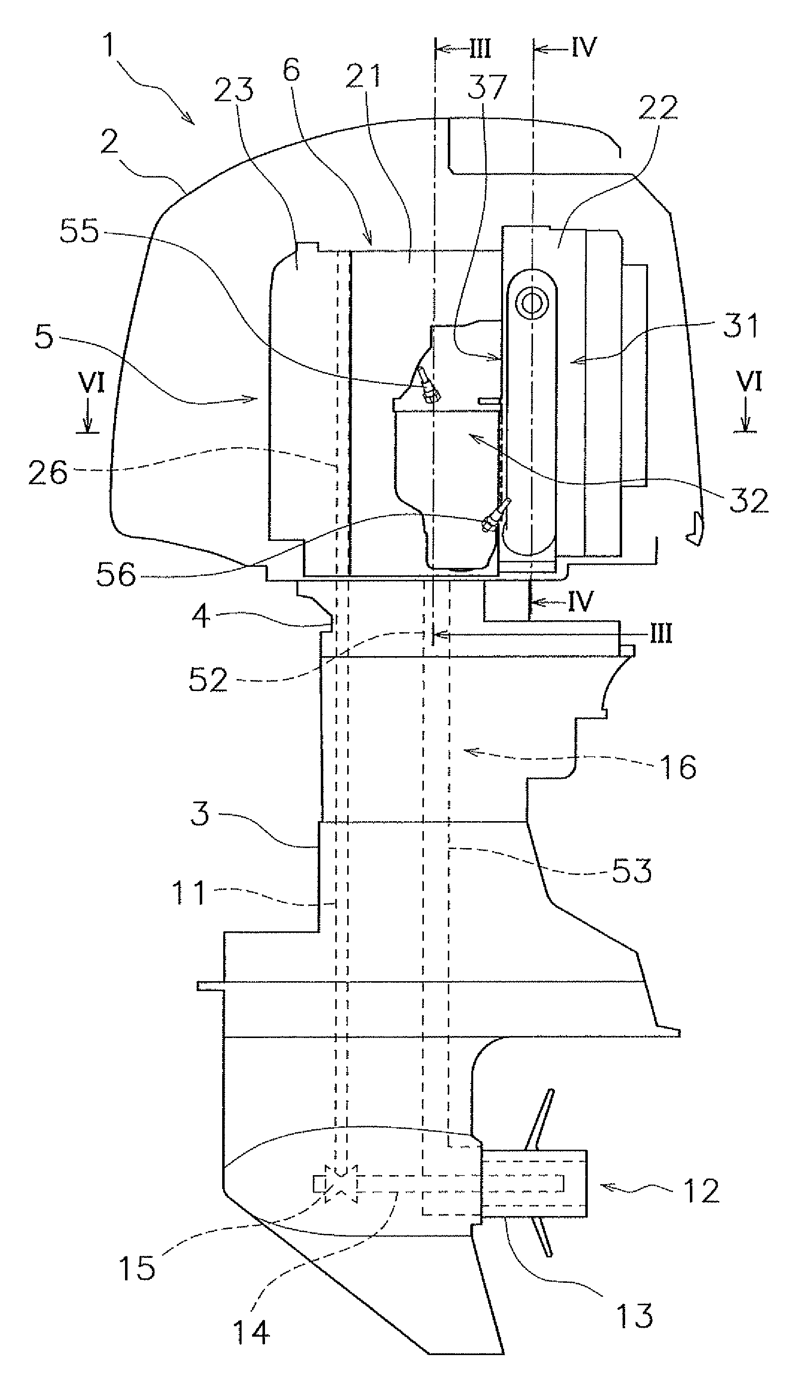
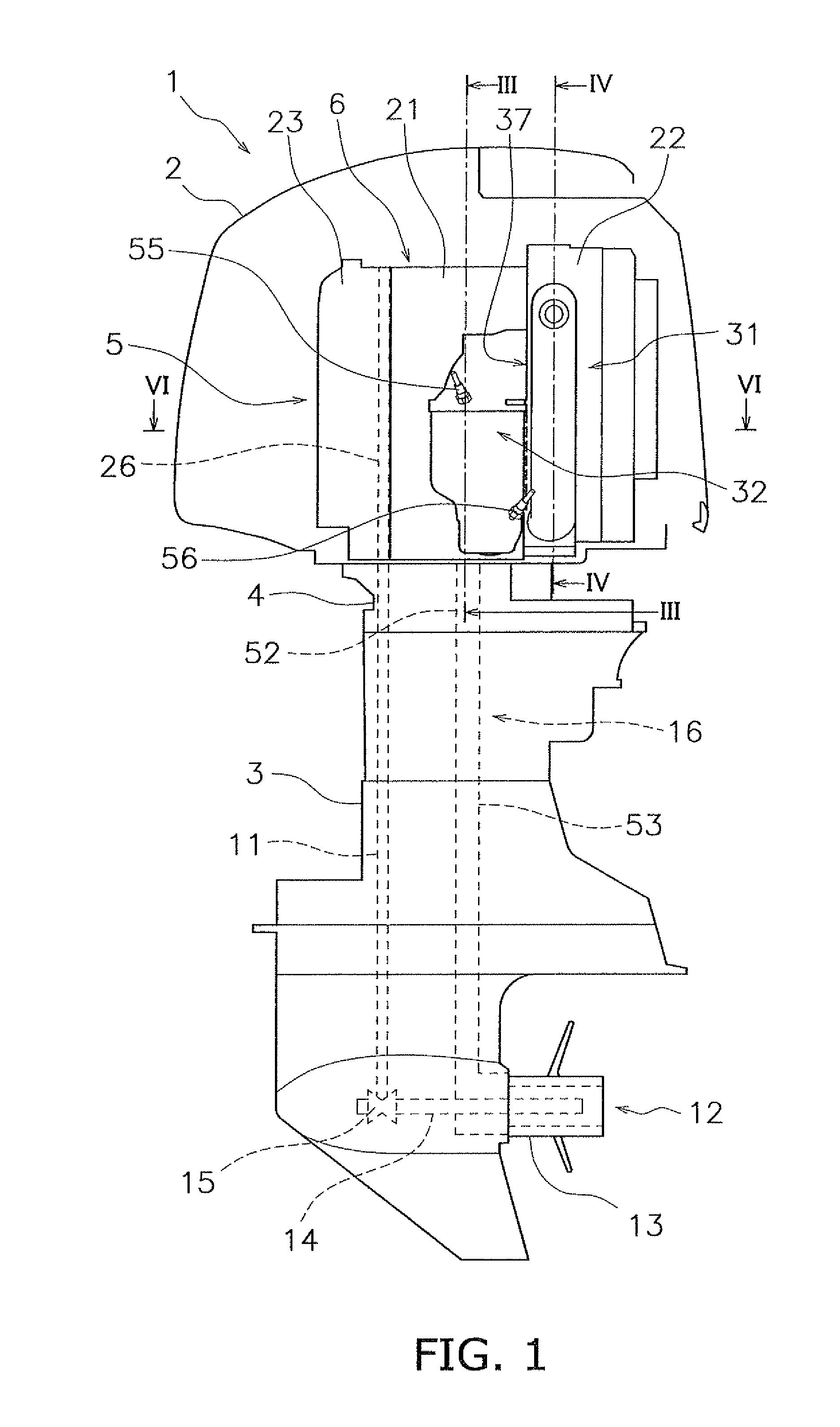
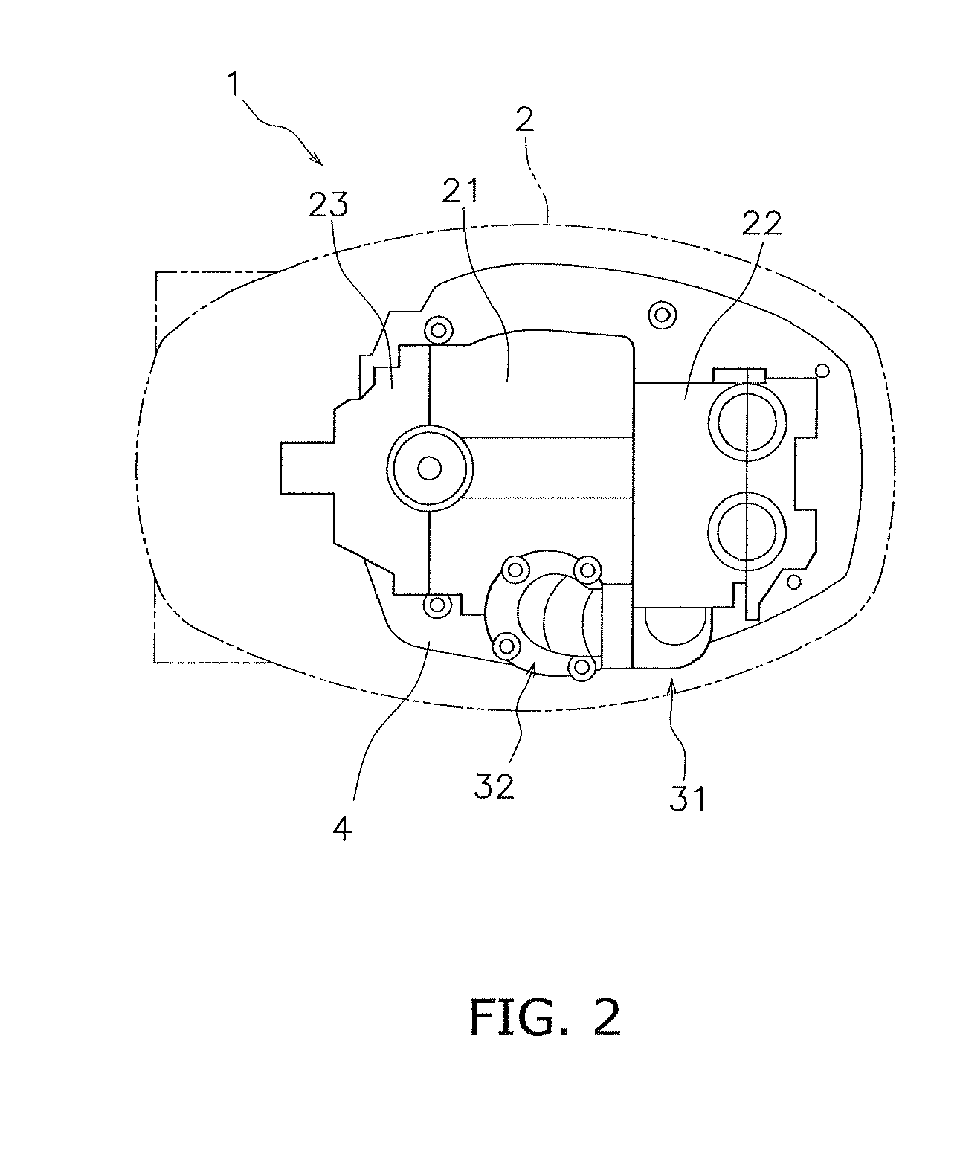
[0022]FIG. 1 is a side view depicting an outboard motor 1 according to a preferred embodiment of the present invention. FIG. 2 is a top view of the outboard motor 1. As shown in FIGS. 1 and 2, the outboard motor 1 according to the present preferred embodiment includes an upper casing 2, a lower casing 3, an exhaust guide portion 4, and an engine unit 5. For ease of understanding, the upper casing 2 is shown in cross section in FIG. 1. In FIG. 2, the outer contours of the upper casing 2 are shown by double-dot and dash lines. The upper casing 2, the lower casing 3, and the engine unit 5 are fixed to the exhaust guide portion 4.
[0023]The engine unit 5 is disposed inside the upper casing 2. The engine unit 5 includes an engine 6, an exhaust manifold 31, and a catalytic converter 32. A drive shaft 11 is disposed inside the lower casing 3. The drive shaft 11 is disposed along the vertical direction inside the lower casing 3. The drive shaft 11 is fixed to a crankshaft 26 of the engine 6....
PUM
| Property | Measurement | Unit |
|---|---|---|
| retaining structure | aaaaa | aaaaa |
| structure | aaaaa | aaaaa |
| temperature | aaaaa | aaaaa |
Abstract
Description
Claims
Application Information