Fluid line connection safeguard

a safeguard and fluid line technology, applied in the direction of sleeves/socket joints, pipe joints, couplings, etc., can solve the problems of reducing the flexibility of laying pipes, requiring time-consuming fitting operations, and complex welding work, so as to increase the clamping or tilting, and increase the clamping action

Inactive Publication Date: 2017-07-27
CENTTHERM SYSTTECHN
View PDF0 Cites 0 Cited by
  • Summary
  • Abstract
  • Description
  • Claims
  • Application Information

AI Technical Summary

Benefits of technology

[0024]In order to increase the clamping action of the fluid line connection safeguard on the outer circumference of the second fluid line part, it is advantageous that the clamping body—in particular in the assembly position of the socket connection—is arranged with a certain pre-clamping effect on the second fluid line part. In addition to this certain pre-clamping, according to one embodiment of the invention the internal contour of the through opening of the clamping body is sharp-edged or is formed as a friction surface, in order to increase the clamping or tilting of the fluid line connection safeguard on the outer wall of the fluid line part. For example, in the case of a metal construction of the fluid line connection safeguard the sharp-edged internal contour of the clamping body can easily cut into the outer wall of a fluid line part made, for example, of plastic, which additionally increases the clamping action.

Problems solved by technology

However, such screw connections restrict the flexibility of laying pipes to a certain extent and, furthermore, require time-consuming fitting operations.
These flange leaves or flanges are usually welded to the pipe, which entails complex welding work.
Furthermore, socket connections for uninterrupted connection of pipes or fluid line parts are known from the prior art.
A disadvantage of these socket connections is that they are not generally self-locking and are not designed to withstand tensile forces, so that there is risk that when tensile loading takes effect the pipes or fluid line parts to be connected slide apart and release the pipe connection or fluid line connection.
However, it is a disadvantage that visual checking of the security in the form of the clamping ring is not possible, since the clamping ring is arranged in the interior of the pipe connection between the pipes and checking is only possible when the pipe connection is released.
Furthermore, the use of such a clamping element has the disadvantage that the clamping element does not take effect immediately, but only after a certain run-up distance, so that sealing of the connection is not guaranteed in every case.
In addition, such generally elastic clamping elements only withstand a certain tensile force and are not suitable for greater tensile loads.
Thus in particular in the case of pressurized socket connections there is a risk that the socket connection is released under tensile loading.
However, this fluid line connection safeguard has the disadvantage that it is designed only for a single nominal width of the fluid line part and thus can only be used for an application with a specific nominal width.
This clamping causes the fluid line connection safeguard to tilt further in the event of any sliding apart of the fluid line connection and thus ultimately a type of self-locking occurs.
Due to this configuration the adjustment means can be fixed to the first clamping body element in a defined manner only in the end regions, whereas the adjustment slot allows a movement of the adjustment means from end region to end region, but fixing of the adjustment means along the adjustment slot is not possible.

Method used


Image

  • Fluid line connection safeguard
  • Fluid line connection safeguard
  • Fluid line connection safeguard

Examples


Embodiment Construction

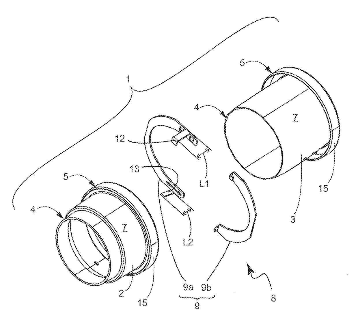
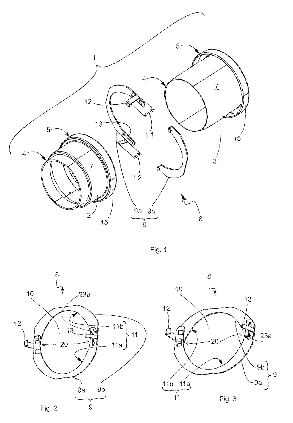
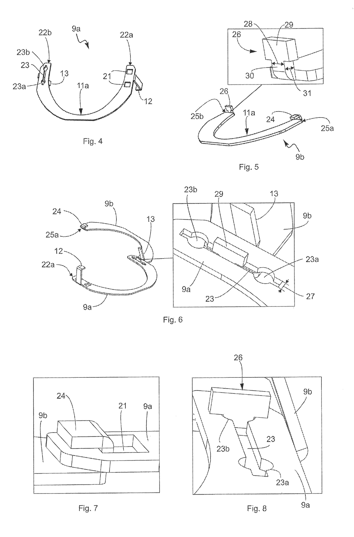
[0042]In the specific exemplary embodiment of the present invention a pipe connection is described below. It will be understood that the invention is not limited only to such a pipe connection and a fluid line connection safeguard which fixes this pipe connection, but connections of any fluid line parts or shaped parts / shaped pieces, such as for example pipes, pipe bends, T-pieces, Y-pieces, coupling sleeves, U-pipe, pipe branches, reductions, pipe stubs and the like, are covered.

[0043]FIGS. 1 and 9 to 11 show a pipe connection or pipe connection arrangement designated overall by 1, which constitutes the socket connection 1 according to the invention. The socket connection 1 or pipe connection 1 comprises a first pipe or fluid line part 2 and a second pipe or fluid line part 3, which in the illustrated exemplary embodiment are both of circular cylindrical construction and are made of plastic. Consideration may be given, for example, to polypropylene as a material for the pipes, wher...


PUM


Abstract

A fluid line connection safeguard for axial connection of a socket-shaped end portion of a first fluid line part with an end portion of a second fluid line part formed as a spigot end includes an annular clamping body which has a through opening with an overall internal contour and at least two clamping body elements forming a clamping body, wherein a respective clamping body element has a circular segment-shaped internal contour and the circular segment-shaped internal contours of the at least two clamping body elements form the overall internal contour, and wherein the at least two clamping body elements are connected to one another by means of an adjusting connection in such a way that the overall internal contour is adjustable to at least two different diameters.

Description

BACKGROUND AND BRIEF DESCRIPTION[0001]The invention relates to a fluid line connection safeguard for axial connection of a socket-shaped end portion of a first fluid line part with an end portion of a second fluid line part formed as a spigot end, wherein the fluid line connection safeguard comprises an annular clamping body which has a through opening with an overall internal contour adapted to the external diameter of the second fluid line part for insertion of the second fluid line part, wherein at least one hook-shaped retaining element extending in the axial direction for engagement with the end portion of the first fluid line part is formed on the clamping body, wherein at least one stem-like spacer extending in the axial direction is formed on the clamping body, and wherein the at least one retaining element and the at least one spacer extend in the same axial direction.[0002]The invention also relates to a socket connection which has a first fluid line part with a socket-sha...

Claims


Application Information

Patent Timeline
Patent Type & Authority Applications(United States)
IPC IPC(8): F16L21/08
CPCF16L21/08F16L37/1205
Inventor GOTTRE, ALEXANDERLIESE, RALF
Owner CENTTHERM SYSTTECHN
Why Eureka
Try Eureka