Pneumatic clamping device for feeding machine

A pneumatic clamping and blanking machine technology, applied in metal processing and other directions, can solve the problems of easy deviation of materials and affect blanking accuracy, and achieve the effect of improving contact area, improving reliability, and being easy to achieve.

Pending Publication Date: 2020-02-07
XINAN TOOLS GUIZHOU PROV
View PDF0 Cites 0 Cited by
  • Summary
  • Abstract
  • Description
  • Claims
  • Application Information

AI Technical Summary

Problems solved by technology

[0003] The purpose of the present invention is to provide a pneumatic clamping device for a blanking machine to solve the problem in the prior art that the material is easily shifted and affects the blanking accuracy

Method used


Image

  • Pneumatic clamping device for feeding machine
  • Pneumatic clamping device for feeding machine
  • Pneumatic clamping device for feeding machine

Examples


Embodiment Construction

[0013] The technical solution of the present invention will be further described below in conjunction with the accompanying drawings, but the scope of protection claimed by the present invention is not limited thereto.

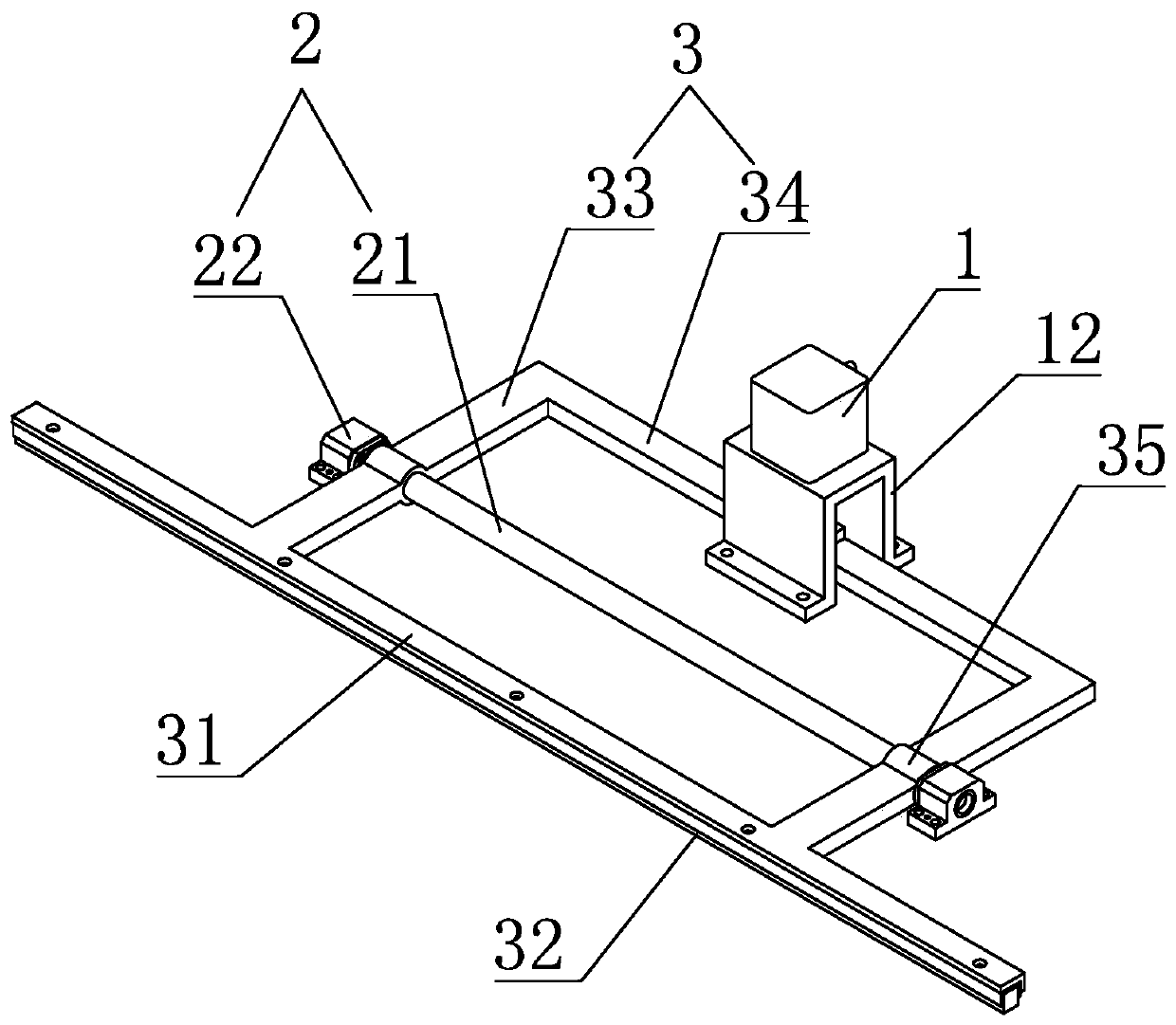
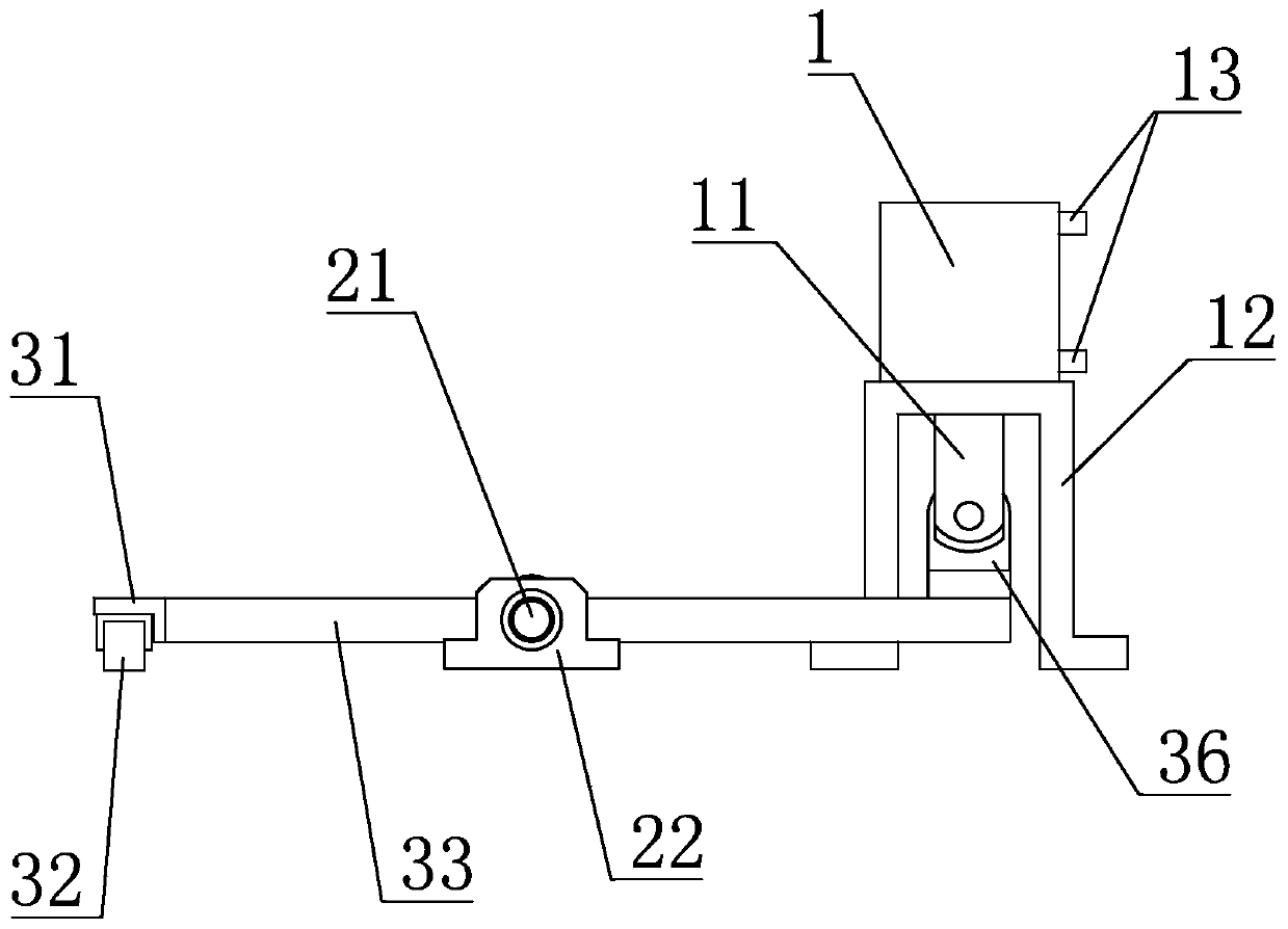
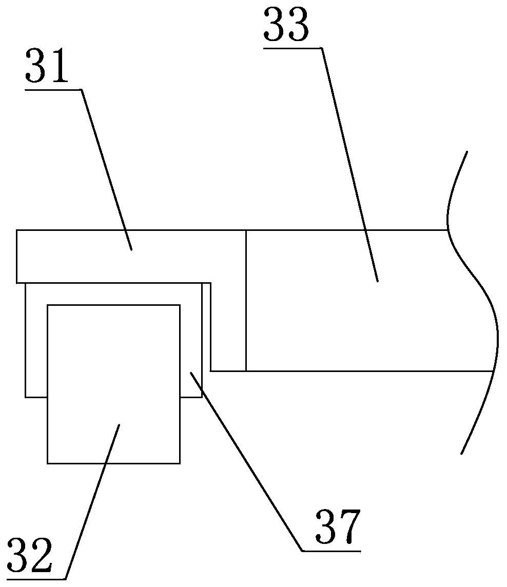
[0014] refer to Figure 1-3 , a pneumatic clamping device for a blanking machine, including a cylinder 1, a fulcrum frame 2 and a press frame 3, the middle part of the press frame 3 is rotatably connected to the fulcrum frame 2, and one end of the press frame 3 is connected to the The cylinder rod 11 of the cylinder 1 is hinged, and is driven to move up and down by the cylinder 1 , the other end is provided with a workpiece pressing plate 31 , and the lower side of the workpiece pressing plate 31 is provided with a rubber pad 32 .

[0015] Specifically, the upper and lower ends of the cylinder 1 are provided with air pipe joints 13 for connecting the air pipes, and the two air pipes connected by the two air pipe joints 13 are connected to the two ports on one ...


PUM


Abstract

The invention belongs to the field of feeding machines, and particularly relates to a pneumatic clamping device for a feeding machine, which includes an air cylinder, a pivot frame and a pressing frame, wherein the middle part of the pressing frame is rotationally connected onto the pivot frame; one end of the pressing frame is hinged with an air cylinder rod of the air cylinder; a workpiece pressing plate is arranged at the other end of the pressing frame; and a rubber blanket is arranged on the lower side of the workpiece pressing plate. In the course of action, the pressing frame takes thepivot frame as a pivot, so as to form a lever, and the air cylinder serves as the power of the lever to quickly drive the workpiece pressing plate to move vertically, as a result, releasing and clamping are realized, and the structure is simple, and the clamping device is easy to realize; as the rubber blanket is arranged on the lower side of the workpiece pressing plate, and is equal to the workpiece pressing plate in length, the entire workpiece pressing plate is in contact with and compresses a material through the rubber blanket, and the deformability of the rubber blanket is high, the contact area of the rubber blanket and a workpiece to be compressed is enlarged, so that the friction force is increased, as a result, the material to be compressed is not easy to move, and the reliability of compressing the material is improved, movement or deflection during the feeding process is avoided, and the feeding accuracy is guaranteed.

Description

technical field [0001] The invention belongs to the field of blanking machines, and in particular relates to a pneumatic clamping device for a blanking machine. Background technique [0002] The clamping device of the blanking machine is used to compress the material when cutting and blanking, but the structure of the existing clamping device of the blanking machine is relatively complicated, and the reliability of compressing the material is poor, and the material is easy to move or deviate during the blanking process. Shift, thus affecting the accuracy of blanking. Therefore, it is necessary to improve and optimize the existing clamping device of the blanking machine. Contents of the invention [0003] The object of the present invention is to provide a pneumatic clamping device for a blanking machine to solve the problem in the prior art that the material is easily shifted and affects the blanking accuracy. [0004] The technical scheme that the present invention real...

Claims


Application Information

Patent Timeline
IPC IPC(8): B23Q7/00
CPCB23Q7/00
Inventor 李玲华蒋道顺
Owner XINAN TOOLS GUIZHOU PROV
Why Eureka
Try Eureka