Heat exchanger with enhanced heat transfer

Inactive Publication Date: 2017-07-27
HAMILTON SUNDSTRAND CORP
View PDF4 Cites 0 Cited by
  • Summary
  • Abstract
  • Description
  • Claims
  • Application Information

AI Technical Summary

Benefits of technology

[0011]The device can further include a first section and a second section. Each of the first and second sections including the flow passages, wherein each flow passage includes heat transfer elements positioned to provide increased heat transfer in a direction from the inlet to the outlet. The first and second sections can include plate sections in a stacked arrangement with each of the flow passages having a bend at an outer edge of the heat exchange device configured to return high pressure

Problems solved by technology

Secondary heat transfer elements within and adjacent each flow passage have heat transfer characteristics varying in the direction of the hot fluid flow such tha

Method used


Image

  • Heat exchanger with enhanced heat transfer
  • Heat exchanger with enhanced heat transfer
  • Heat exchanger with enhanced heat transfer

Examples


Example

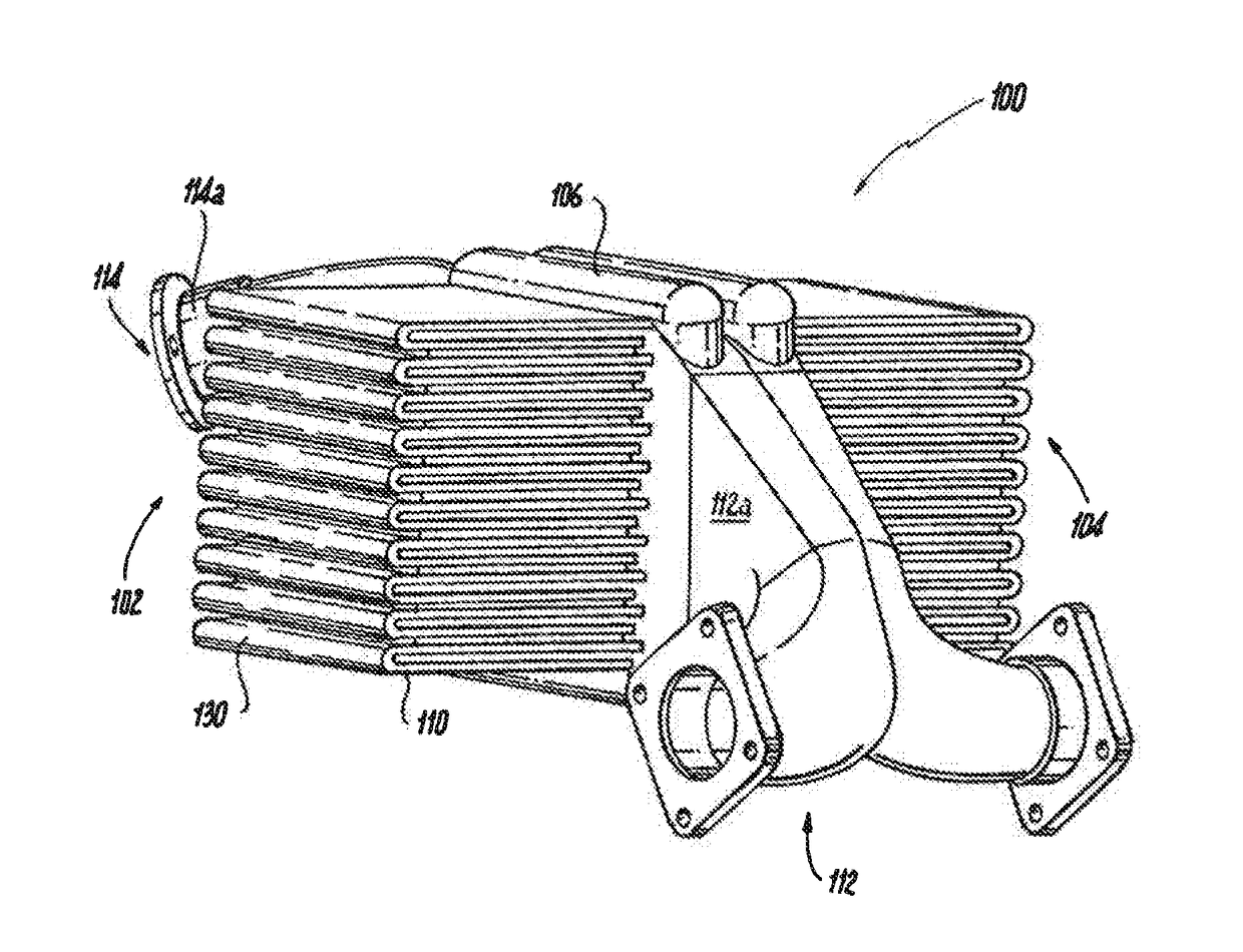
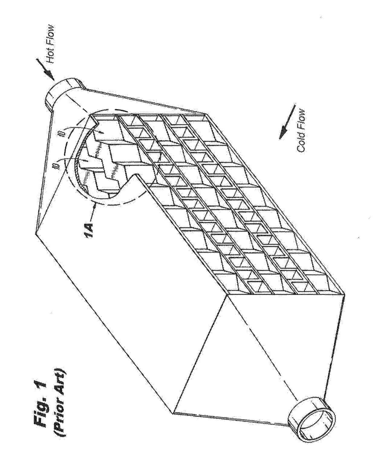
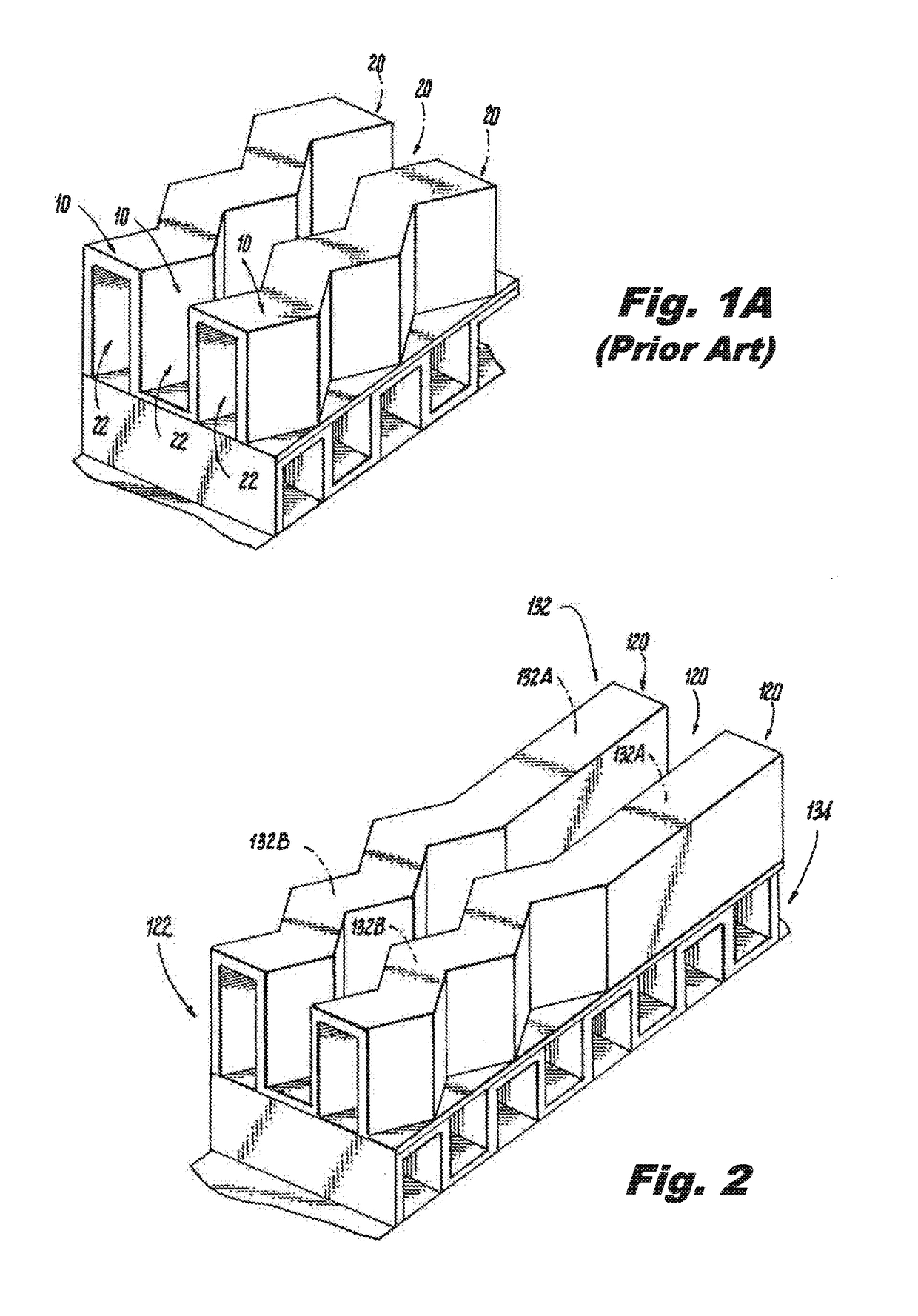
[0019]Reference will now be made to the drawings wherein like reference numerals identify similar structural features or aspects of the subject disclosure. For purposes of explanation and illustration, and not limitation, a partial view of an exemplary embodiment of a heat exchange device in accordance with the disclosure is shown in FIG. 2 and is designated generally by reference character 100. Other embodiments of the heat exchange device in accordance with the disclosure, or aspects thereof, are provided in FIGS. 1-3, as will be described. The systems and methods described herein can be used in turbine engines exposed to high pressure and high temperatures, for example in aerospace application. The present disclosure provides for a device that reduces the product of heat transfer coefficient and heat transfer surface area in regions of the device where metal temperatures must be limited to meet life requirements, while still maintaining a large product of heat transfer coefficien...


PUM


Abstract

A heat exchange device includes a plurality of flow passages. Each flow passage has an inlet and an outlet configured for hot fluid flow in a direction from the inlet to the outlet. Secondary heat transfer elements within and adjacent each flow passage have heat transfer characteristics varying in the direction of the hot fluid flow such that peak metal temperatures limit creep to acceptable values and such that transient thermal stresses are limited to values producing acceptable life of the device.

Description

BACKGROUND OF THE INVENTION[0001]1. Field of the Invention[0002]The present disclosure relates to heat exchangers, and more particularly to plate-stack heat exchangers.[0003]2. Description of Related Art[0004]Heat exchangers such as, for example, tube-shell heat exchangers, are typically used in aerospace turbine engines and other high temperature applications. These heat exchangers are used to transfer thermal energy between two fluids without direct contact between the two fluids. In particular, a primary fluid is typically directed through a fluid passageway of the heat exchanger, while a cooling or heating fluid is brought into external contact with the fluid passageway. In this manner, heat may be conducted through walls of the fluid passageway to thereby transfer energy between the two fluids. One typical application of a heat exchanger is related to an engine and involves the cooling of air drawn into the engine and / or exhausted from the engine.[0005]However, typical tube she...

Claims


Application Information

Patent Timeline
IPC IPC(8): F28F13/14F28F3/02F28F9/02F28D1/047
CPCF28F13/14F28D1/0476F28F3/025F28F2265/10F28F9/0246F28D2001/0266F28F2215/04F28F3/02F28D1/0408F28D9/0062F28F1/126F28F9/02F28F2009/029
Inventor SCHWALM, GREGORY K.
Owner HAMILTON SUNDSTRAND CORP
Why Eureka
Try Eureka