

Pot rack and gas stove
A pot rack and flue gas emission technology, applied in the field of kitchen appliances, can solve the problems of heat loss, reduce the thermal efficiency of gas cookers, etc., and achieve the effects of reducing heat loss, increasing heat exchange, and improving thermal efficiency
- Summary
- Abstract
- Description
- Claims
- Application Information
AI Technical Summary
Problems solved by technology
Method used
Image

Examples
Embodiment 1
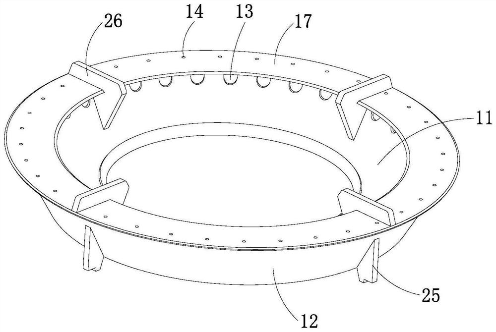
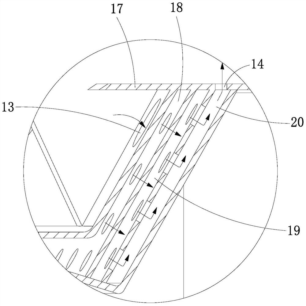
[0035] see Figure 1 to Figure 3 As shown, this embodiment provides a pan support, including a pan support body, a deflector 17 and a heat exchange structure 15, the inner ring surface of the pan support body is provided with a flue gas inlet 13; the deflector 17 and the pan support body Fixedly connected, and the deflector 17 is located above the flue gas inlet 13; the deflector 17 is provided with a flue gas discharge port 14; the heat exchange structure 15 is fixedly connected between the inner ring surface and the outer ring surface of the pan support body In the inner cavity, and the heat exchange structure 15 is located between the flue gas inlet 13 and the flue gas discharge port 14, the heat exchange structure 15 is provided with a heat exchange hole 16, and the flue gas inlet 13 and the flue gas discharge port 14 are connected to the heat exchange hole 16 connected.
[0036] Based on this structure, when using the pan support provided in this embodiment, the pan supp...
Embodiment 2
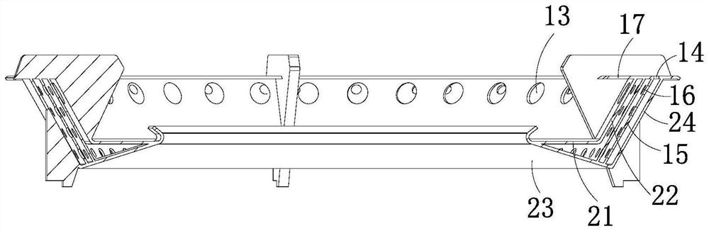
[0055] see Figure 4 to Figure 6 As shown, this embodiment also provides a pan support, including a pan support body, a deflector 17 and a heat exchange structure 15, the inner ring surface of the pan support body is provided with a flue gas inlet 13; the deflector 17 and the pan support The body is fixedly connected, and the deflector 17 is located above the flue gas inlet 13; the outer ring surface of the pot frame body is provided with a gas discharge port 14; the heat exchange structure 15 is fixedly connected to the inner ring surface and the outer ring surface of the pot frame body and the heat exchange structure 15 is located between the flue gas inlet 13 and the flue gas discharge port 14, the heat exchange structure 15 is provided with heat exchange holes 16, the flue gas inlet 13 and the flue gas discharge port 14 are connected to the The heat exchange holes 16 are connected.
[0056] Based on this structure, when using the pan support provided in this embodiment, t...
PUM
 Abstract
Description
Claims
Application Information