

Lens system and camera system including the lens system
a technology applied in the field of lens system and camera system, can solve the problem of large image sensor area unused
- Summary
- Abstract
- Description
- Claims
- Application Information
AI Technical Summary
Benefits of technology
Problems solved by technology
Method used
Image

Examples
embodiments 1 through 4
[1. Configurations]
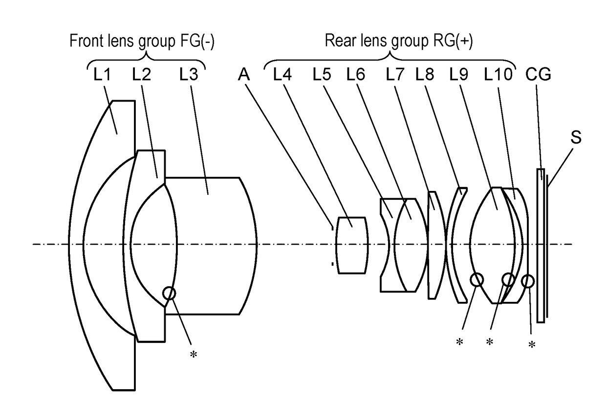
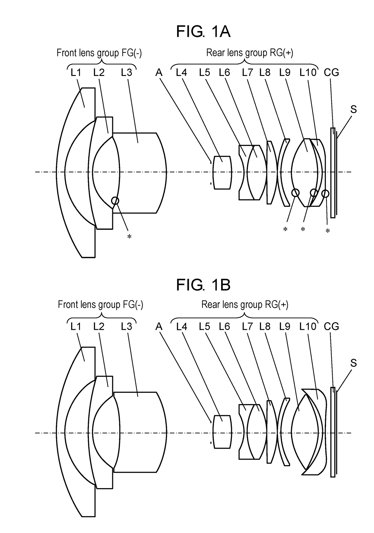
[0054]FIG. 1A is a layout of lens elements in a YZ cross section, illustrating an infinite focus state of a lens system according to non-limiting Embodiment 1 (Numerical Example 1). FIG. 1B is a layout of the lens elements in an XZ cross section, illustrating an infinite focus state of the lens system according to Embodiment 1 (Numerical Example 1).
[0055]FIG. 3A is a layout of lens elements in a YZ cross section, illustrating an infinite focus state of a lens system according to non-limiting Embodiment 2 (Numerical Example 2). FIG. 3B is a layout of the lens elements in an XZ cross section, illustrating an infinite focus state of the lens system according to Embodiment 2 (Numerical Example 2).
[0056]FIG. 5A is a layout of lens elements in a YZ cross section, illustrating an infinite focus state of a lens system according to non-limiting Embodiment 3 (Numerical Example 3). FIG. 5B is a layout of the lens elements in an XZ cross section, illustrating an infinite focu...
embodiment 1
[0062]As illustrated in FIG. 1A and FIG. 1B, front lens group FG of the lens system according to Embodiment 1 includes, in order from the object side to the image surface side, meniscus-shaped first lens element L1 having negative power and a convex surface facing the object, meniscus-shaped second lens element L2 having negative power and a convex surface facing the object, and meniscus-shaped third lens element L3 having positive power and a convex surface facing the image surface. The surface of third lens element L3 facing the object is a freeform surface defined by an XY polynomial.
[0063]Here, third lens element L3 is a freeform surface lens having a shape symmetric about the horizontal axis (i.e., an axis passing through the optical axis and parallel to the long side of the image sensor. The same applies hereinafter.) and the vertical axis (i.e., an axis passing through the optical axis and parallel to the short side of the image sensor. The same applies hereinafter.), and fir...
embodiment 2
[0067]As illustrated in FIG. 3A and FIG. 3B, front lens group FG of the lens system according to Embodiment 2 includes, in order from the object side to the image surface side, meniscus-shaped first lens element L1 having negative power and a convex surface facing the object, meniscus-shaped second lens element L2 having negative power and a convex surface facing the object, and meniscus-shaped third lens element L3 having positive power and a convex surface facing the image surface. The surface of third lens element L3 facing the object is a freeform surface defined by an XY polynomial.
[0068]Here, third lens element L3 is a freeform surface lens having a shape symmetric about the horizontal axis and the vertical axis, and first lens element L1 and second lens element L2 are lens elements which are axially symmetric about the optical axis.
[0069]Rear lens group RG of the lens system according to Embodiment 2 includes, in order from the object side to the image surface side, biconvex ...
PUM
 Abstract
Description
Claims
Application Information