Wafer edge ring lifting solution

a technology of lifting solution and edge ring, which is applied in the direction of electrical equipment, basic electric elements, electric discharge tubes, etc., can solve the problems of poor processing, eroded traditional edge rings over time, and the plasma driving the etching process may not be uniformly distributed across the substrate surfa

Active Publication Date: 2017-07-27
APPLIED MATERIALS INC
View PDF9 Cites 123 Cited by
  • Summary
  • Abstract
  • Description
  • Claims
  • Application Information

AI Technical Summary

Problems solved by technology

During etching processes, a plasma, which drives the etching process, may not be uniformly distributed across the substrate surface.
This non-uniformity contributes to poor processing results.
However, traditional edge rings erode over time.
As the edge ring erodes, plasma uniformity across the substrate surface decreases, thereby negatively affecting substrate processing.
However, the frequent replacement of edge rings results in undesirable downtime for preventative maintenance, and leads to increased costs for consumable components such as the edge rings.

Method used


Image

  • Wafer edge ring lifting solution
  • Wafer edge ring lifting solution
  • Wafer edge ring lifting solution

Examples


Embodiment Construction

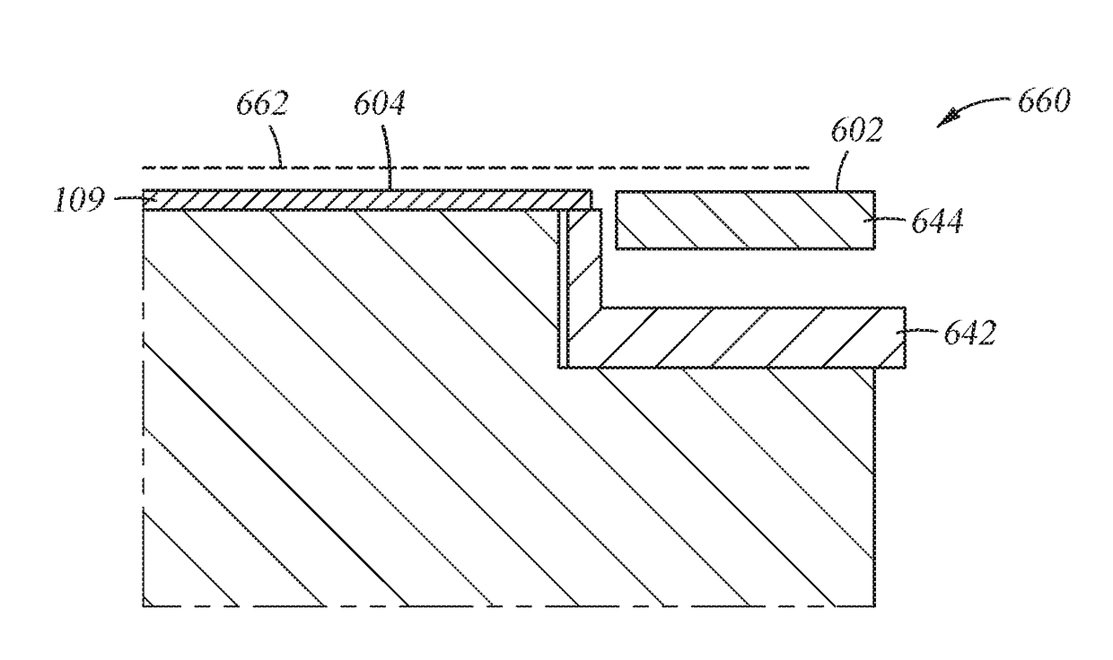
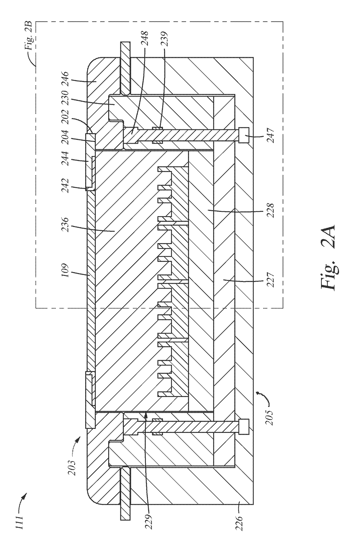
[0025]Apparatuses including a height-adjustable edge ring, and methods for use thereof are described herein. In one example, a substrate support assembly includes a height-adjustable edge ring, and the substrate support assembly is located within a process chamber. The substrate support assembly includes an electrostatic chuck, an edge ring positioned on a portion of the electrostatic chuck, and one or more actuators to adjust the height of the edge ring via one or more push pins. The height-adjustable edge ring can be used to compensate for erosion of the edge ring over time. In addition, the height-adjustable edge ring can be removed from the process chamber via a slit valve opening without venting and opening the process chamber. The height-adjustable edge ring can be tilted by the one or more actuators in order to improve azimuthal uniformity at the edge of the substrate.

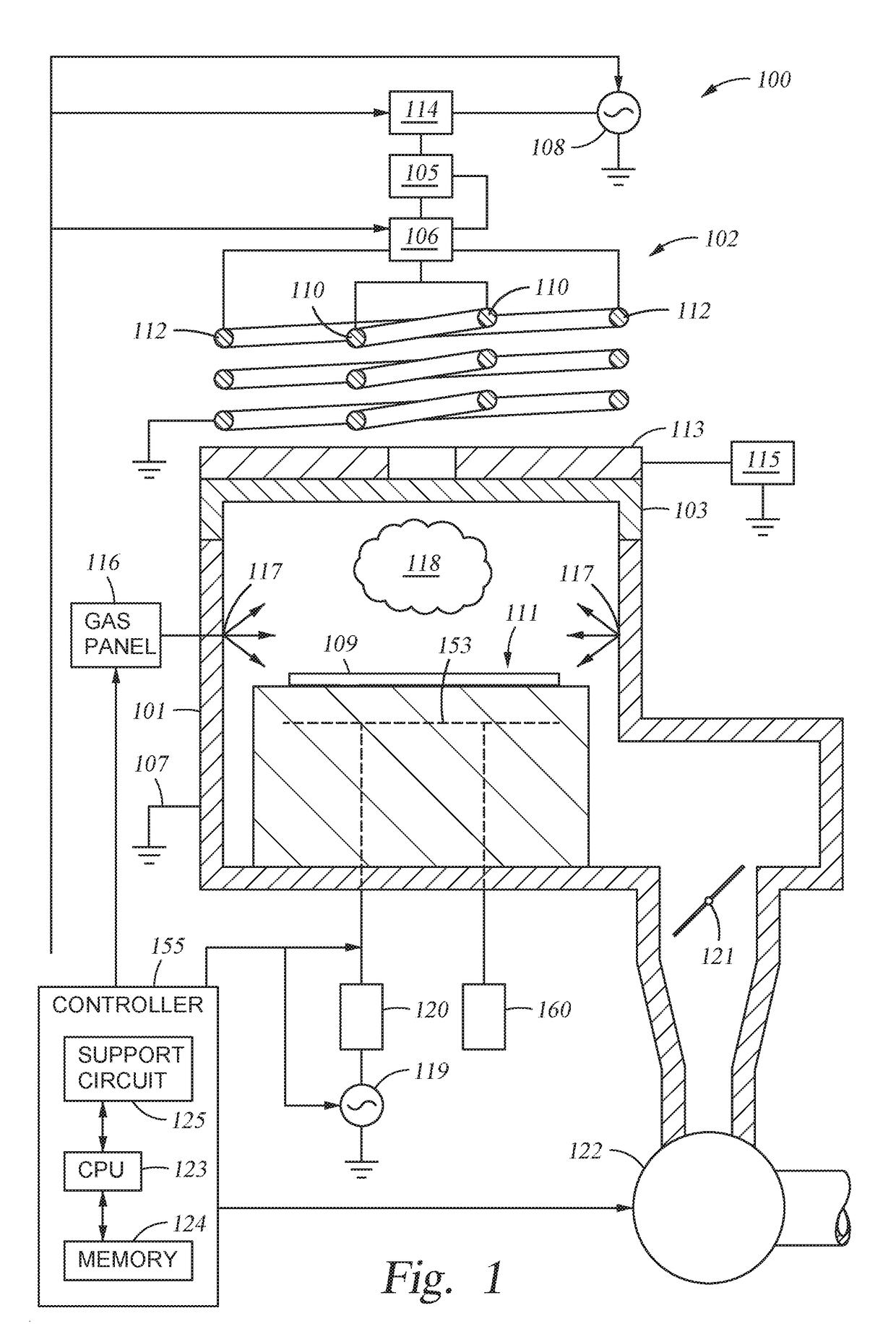
[0026]FIG. 1 is a schematic sectional view of a process chamber 100, according to one example of the disclosu...


PUM


Abstract

Apparatuses including a height-adjustable edge ring, and methods for use thereof are described herein. In one example, a substrate support assembly includes a height-adjustable edge ring, and the substrate support assembly is located within a process chamber. The substrate support assembly includes an electrostatic chuck, an edge ring positioned on a portion of the electrostatic chuck, and one or more actuators to adjust the height of the edge ring via one or more push pins. The height-adjustable edge ring can be used to compensate for erosion of the edge ring over time. In addition, the height-adjustable edge ring can be removed from the process chamber via a slit valve opening without venting and opening the process chamber. The height-adjustable edge ring can be tilted by the one or more actuators in order to improve azimuthal uniformity at the edge of the substrate.

Description

CROSS-REFERENCE TO RELATED APPLICATIONS[0001]This application claims benefit of U.S. Provisional Patent Application Ser. No. 62 / 287,038, filed on Jan. 26, 2016, and Indian Provisional Application No. 201641019009, filed on Jun. 2, 2016, each of which is herein incorporated by reference in its entirety.BACKGROUNDField[0002]Examples of the present disclosure generally relate to apparatuses for processing substrates, such as semiconductor substrates. More particularly, a process kit and methods for use thereof, are disclosed.Description of the Related Art[0003]In the processing of substrates, such as semiconductor substrates and display panels, a substrate is placed on a support in a process chamber while suitable process conditions are maintained in the process chamber to deposit, etch, form layers on, or otherwise treat surfaces of the substrate. During etching processes, a plasma, which drives the etching process, may not be uniformly distributed across the substrate surface. The no...

Claims


Application Information

Patent Timeline
Patent Type & Authority Applications(United States)
IPC IPC(8): H01L21/687H01J37/32H01L21/683
CPCH01L21/68735H01L21/6833H01J2237/334H01J37/32091H01J37/32715H01L21/67017H01L21/6719H01L21/6831H01L21/68742H01J37/32082H01L21/68721H01L21/6835
Inventor RICE, MICHAEL R.SARODE VISHWANATH, YOGANANDASRINIVASAN, SUNILDHINDSA, RAJINDERBABAYAN, STEVEN E.LUERE, OLIVIERKOOSAU, DENIS M.YOUSIF, IMAD
Owner APPLIED MATERIALS INC
Why Eureka
Try Eureka