
Inline insert molded filter assembly

a filter assembly and insert molding technology, applied in the direction of filter separation, cartridge filter, separation process, etc., can solve the problems of complex manufacturing process, increased complexity and cost, and failure of filter assembly, so as to reduce the cost of inline fitting style filtration and simplify the design. , the effect of fewer failure points

Inactive Publication Date: 2017-08-03
PARKER HANNIFIN CORP
View PDF2 Cites 2 Cited by
  • Summary
  • Abstract
  • Description
  • Claims
  • Application Information

AI Technical Summary

Benefits of technology

The present invention provides an enhanced inline filter assembly with a simplified design and fewer failure points. The filter assembly is made through a process called insert molding, which involves putting filtration components, such as pleated disc filter elements, into a mold and then injecting plastic material to form a sealed filter housing. This process reduces the cost and complexity of the filter assembly and improves its reliability. The filter housing is made of high-performance plastics that can withstand the flow rates and can also reduce the weight of the assembly. The technical effects of this invention are improved efficiency, reduced cost, and enhanced reliability of the inline filter assembly.

Problems solved by technology

Both members are separately manufactured and then joined together in an additional processing step, which results in a complex manufacturing process.
These disadvantages increase complexity and cost, and provide multiple points where the filter assembly can fail.

Method used


Image

  • Inline insert molded filter assembly
  • Inline insert molded filter assembly
  • Inline insert molded filter assembly

Examples


Embodiment Construction

[0017]Embodiments of the present invention will now be described with reference to the drawings, wherein like reference numerals are used to refer to like elements throughout. It will be understood that the figures are not necessarily to scale.

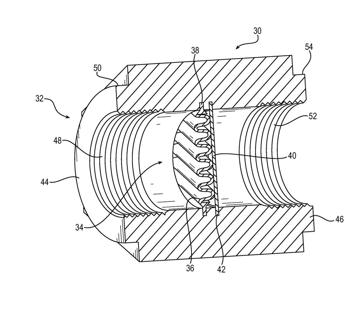
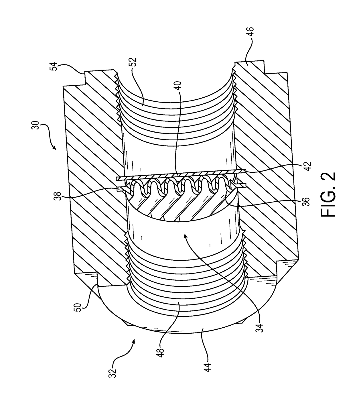
[0018]FIG. 2 is a drawing depicting an enhanced molded inline filter assembly 30 in accordance with embodiments of the present invention. In exemplary embodiments, the filter assembly 30 may include a filter housing 32 formed as a singular unitary component, rather than being constituted of separate parts as in conventional configurations. The filter assembly 30 further may include a filter element 34. In exemplary embodiments of the inline filter assembly, the filter housing may be configured as a singular unitary component having a first end and a second end different from the first end, and defining a fluid flow passage through the filter assembly. The filter element may be fixed within the filter housing and spaced apart from both of the f...


PUM

PropertyMeasurementUnit
sizeaaaaaaaaaa
moldableaaaaaaaaaa
plasticaaaaaaaaaa

Abstract

A filter assembly includes a filter housing configured as a singular unitary component defining a fluid flow passage through the filter assembly. A filter element is fixed within the housing and spaced apart from both ends of the filter housing to filter a fluid as the fluid flows through the filter housing. A method of insert molding a filter assembly includes providing a mold shaped to form the filter housing as a singular unitary component, locating a filter element in the mold at a location corresponding to where the filter element is to be fixed within the filter housing, and injection molding a molten plastic filter housing material around the filter element such that a portion of the filter element is encapsulated by the molten plastic filter housing material to form the filter housing in a manner that bonds the filter element in place within the filter housing. The filter assembly alternatively may be made by 3D printing the filter housing around the filter element.

Description

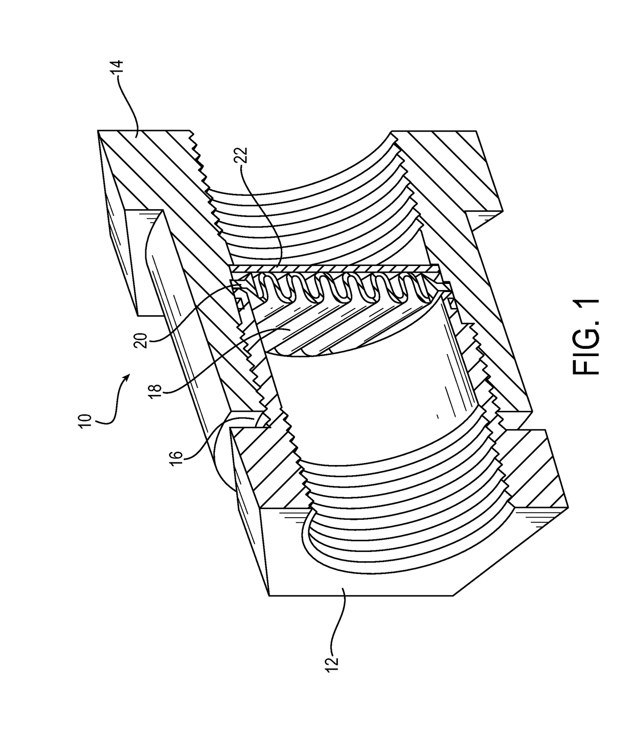
RELATED APPLICATIONS[0001]This application claims the benefit of U.S. Provisional Application No. 62 / 290,546 filed on Feb. 3, 2016, and of U.S. Provisional Application No. 62 / 373,495 filed on Aug. 11, 2016, which are incorporated herein by reference.FIELD OF INVENTION[0002]The present invention relates generally to inline filter assemblies, or filter assemblies that filter a fluid by being inserted inline within a fluid flow pathway to filter the fluid as the fluid flows through said pathway.BACKGROUND OF THE INVENTION[0003]Generally, inline filter assemblies are filter assemblies that filter a fluid by being inserted inline within a fluid flow pathway to filter the fluid as the fluid flows through said pathway. Inline filter assemblies commonly are subjected to relatively high flow rates, such as for example 10 gallons per minute (gpm) or more. An exemplary application is using an inline filter assembly to filter a coolant flow in an electric car coolant system, although inline fil...

Claims


Application Information

Patent Timeline
Patent Type & Authority Applications(United States)
IPC IPC(8): B01D29/01B33Y10/00B01D35/30
CPCB01D29/016B33Y10/00B01D35/30B01D29/012B01D35/02B33Y80/00
Inventor PRINE, ANDREWLUTHER, KENNETH
Owner PARKER HANNIFIN CORP
Learn More