
System and method of operation of twin-tiltrotor helicopter

a technology of twin-tilt-rotor helicopters and systems, which is applied in the direction of vertical landing/take-off aircraft, process and machine control, instruments, etc., can solve the problems of low maneuverability and precision requirements of multi-rotor helicopters, the rear tail rotor of helicopters reduces flight efficiency and does not contribute to lift force,

Inactive Publication Date: 2017-08-03
KING FAHD UNIVERSITY OF PETROLEUM AND MINERALS
View PDF0 Cites 30 Cited by
  • Summary
  • Abstract
  • Description
  • Claims
  • Application Information

AI Technical Summary

Benefits of technology

This patent describes a system and method for operating an air vehicle with two rotors. The system includes a flight computer that sends control parameters to the rotors, including a tilt angle and speed. The air vehicle also has a control panel for receiving flight commands. The method includes operating modes based on the detection of rotor failures or damage, and controlling the angular speeds and tilt angles of the rotors to ensure safe and efficient operation. The technical effect of this patent is to provide a reliable and responsive air vehicle system for a variety of operating modes.

Problems solved by technology

However, unlike a conventional helicopter, a multirotor helicopter employs fixed-pitch blades.
However, the rear tail rotor of helicopters reduces flight efficiency and does not contribute to the lift force.
The multirotor helicopter structure and control in the related art lacks the flexibility to meet the maneuverability and precision requirements needed for control and air vehicle management of manned multirotor helicopter rotors.
Further, multirotor helicopters can be heavy leading to a sluggish or delayed response to a flight command and may require powerful motors to compensate for the rotor weight and slow flight dynamics.

Method used


Image

  • System and method of operation of twin-tiltrotor helicopter
  • System and method of operation of twin-tiltrotor helicopter
  • System and method of operation of twin-tiltrotor helicopter

Examples


Embodiment Construction

[0030]The description set forth below in connection with the appended drawings is intended as a description of various embodiments of the disclosed subject matter and is not necessarily intended to represent the only embodiment(s). In certain instances, the description includes specific details for the purpose of providing an understanding of the disclosed embodiment(s). However, it will be apparent to those skilled in the art that the disclosed embodiment(s) may be practiced without those specific details. In some instances, well-known structures and components may be shown in block diagram form in order to avoid obscuring the concepts of the disclosed subject matter.

[0031]Reference throughout the specification to “one embodiment” or “an embodiment” means that a particular feature, structure, or characteristic described in connection with an embodiment is included in at least one embodiment of the subject matter disclosed. Thus, the appearance of the phrases “in one embodiment” or ...


PUM


Abstract

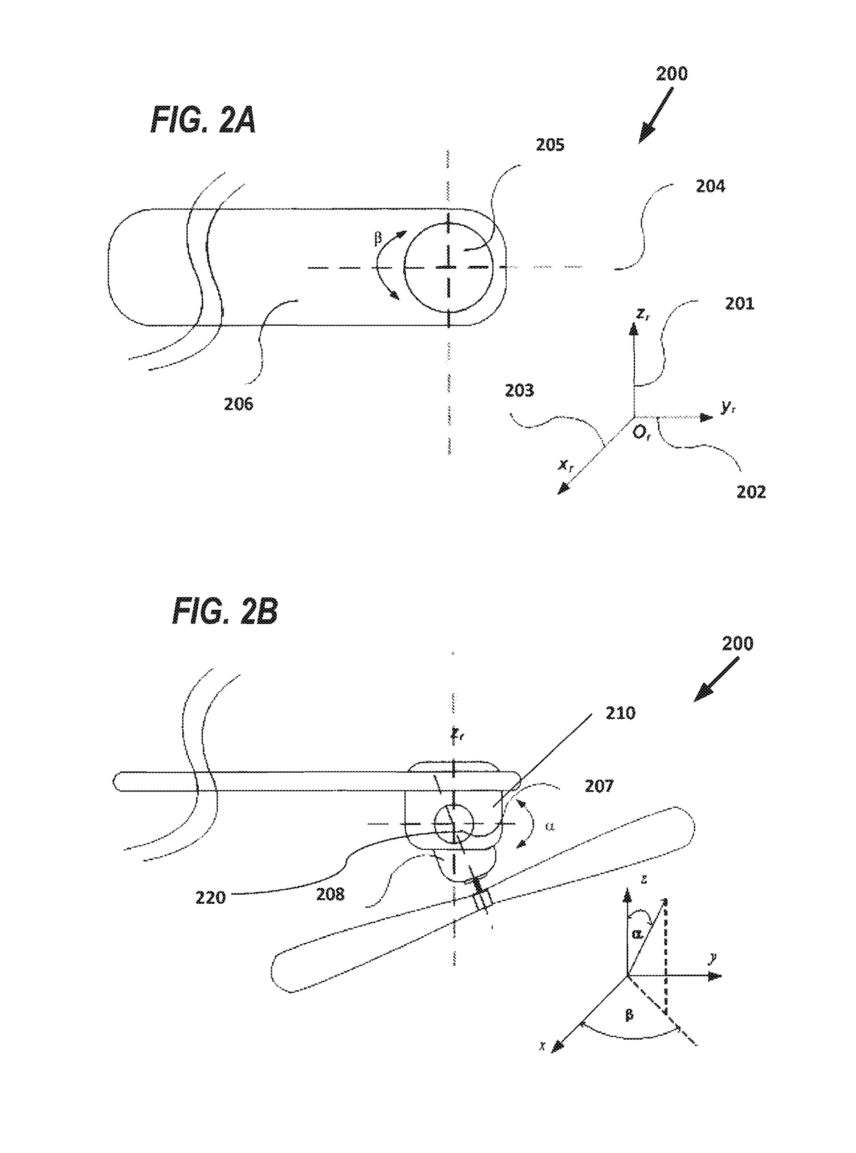
An air vehicle includes a flight computer, a fuselage, and two rotors mounted symmetrically with respect to the fuselage. Each of the two rotors includes a servo mechanism to tilt a respective rotor of the two rotors about two axes of the respective rotor. The flight computer is configured to send control parameters to each of the two rotors, the control parameters including a rotational speed, a first tilt angle about a first axis of the two axes of the respective rotor, and a second tilt angle about a second axis of the two axes of the respective rotor. A method for operating the air vehicle is also provided.

Description

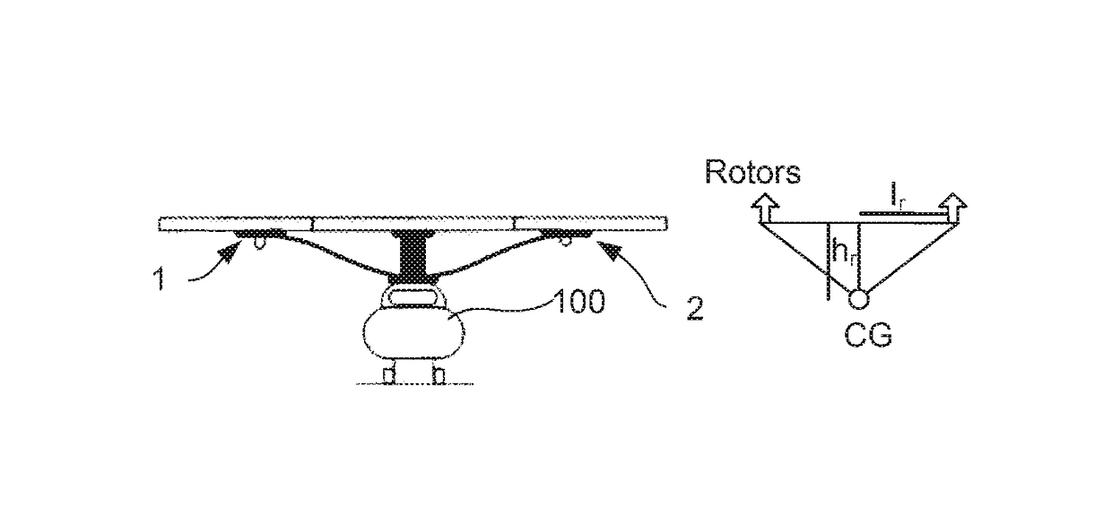
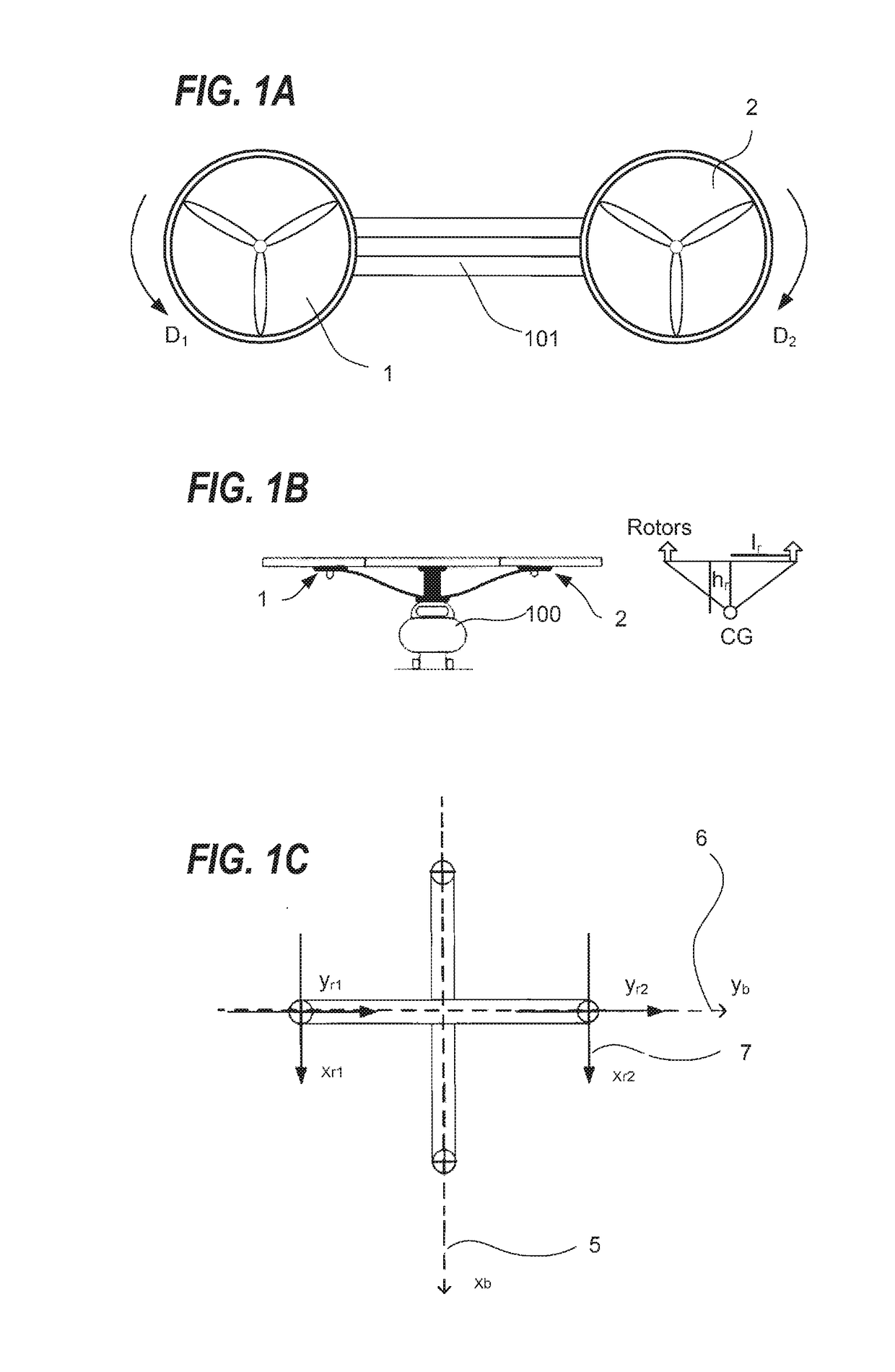
BACKGROUND[0001]Field of the Disclosure[0002]This application relates a system and a method for control of a twin-tiltrotor helicopter. The twin-tiltrotor helicopter (TTH) is lifted and propelled by two rotors. Twin-tiltrotor helicopters are classified as a rotocraft, as opposed to a fixed-wing aircraft, since the twin-tiltrotor helicopters derive lift from the rotation of revolving airfoils.[0003]Description of the Related Art[0004]In conventional helicopters, the rotational speed of the main rotor is usually kept constant, while control of the helicopters' motion is achieved by altering the pitch of the blades. This position dependent pitch is referred to as ‘cyclic’ and the blade's pitch is based on the blade's position in the rotor disk. However, unlike a conventional helicopter, a multirotor helicopter employs fixed-pitch blades.[0005]The control of a multirotor helicopter is achieved by varying the rotational speed of one or more rotors, thereby changing a torque load, thrust,...

Claims


Application Information

Patent Timeline
Patent Type & Authority Applications(United States)
IPC IPC(8): B64C29/00B64C39/02B64C27/54B64C27/56B64C27/57
CPCB64C29/0033B64C27/56B64C2201/146B64C27/54B64C39/024B64C27/57G05D1/0072G05D1/0858B64U2201/20B64U30/297
Inventor ELFEKY, MAHMOUD ABDELMAGIDELSHAFEI, MOUSTAFA
Owner KING FAHD UNIVERSITY OF PETROLEUM AND MINERALS
Learn More