Terrain adaptive flight control

a flight control and adaptive technology, applied in the field of terrain adaptive flight control, can solve problems such as special occurrence of cm

Active Publication Date: 2015-10-08
SIKORSKY AIRCRAFT CORP
View PDF35 Cites 8 Cited by
  • Summary
  • Abstract
  • Description
  • Claims
  • Application Information

AI Technical Summary

Benefits of technology

[0010]FIG. 2 is a schematic view of aircraft flight control systems; and
[0011]FIG....

Problems solved by technology

This type of incident is common and, in fact, CFIT is a leading cause in helicopter crashes.
Occurrence of CM is especia...

Method used


Image

  • Terrain adaptive flight control
  • Terrain adaptive flight control
  • Terrain adaptive flight control

Examples


Embodiment Construction

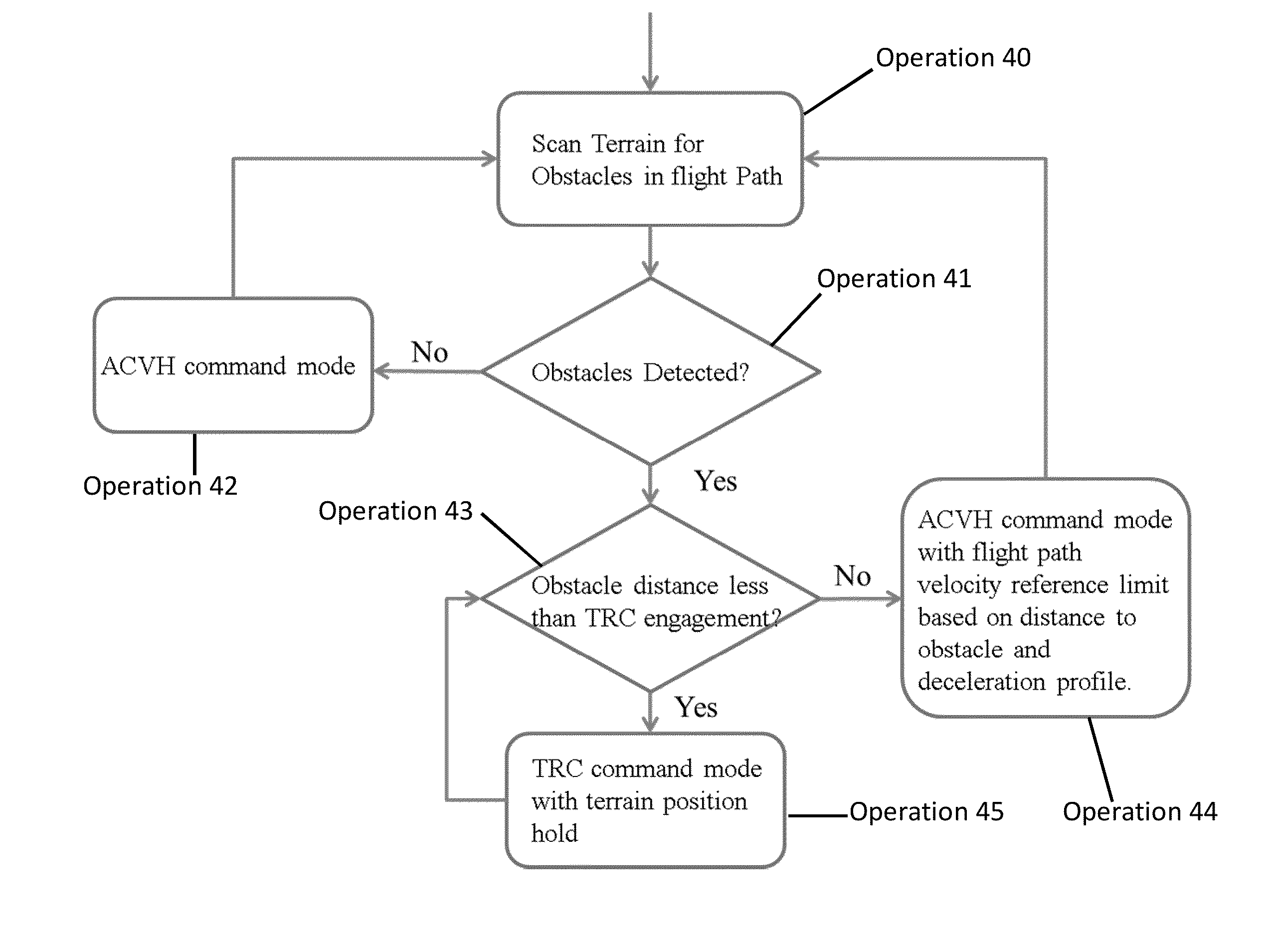
[0013]The description provided below relates to methods and systems to reduce the possibility of CFIT by making aircraft flight controls aware of surrounding terrain and automatically changing the type of control mode based on the aircraft's proximity to the terrain or obstacles in its flight path. In the case that an aircraft's control mode is attitude command velocity hold (ACVH), the trim velocity reference can be limited based on the aircraft's proximity to the terrain or the obstacles in its flight path. The trim velocity would transition to zero as the aircraft approaches, for example, an obstacle. At this point, the control mode transitions to a translational rate command (TRC) type mode where the trim stick position is a position hold mode.

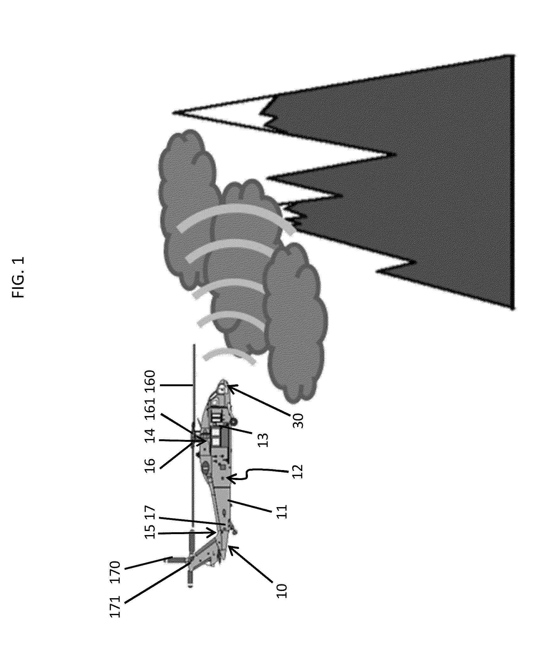
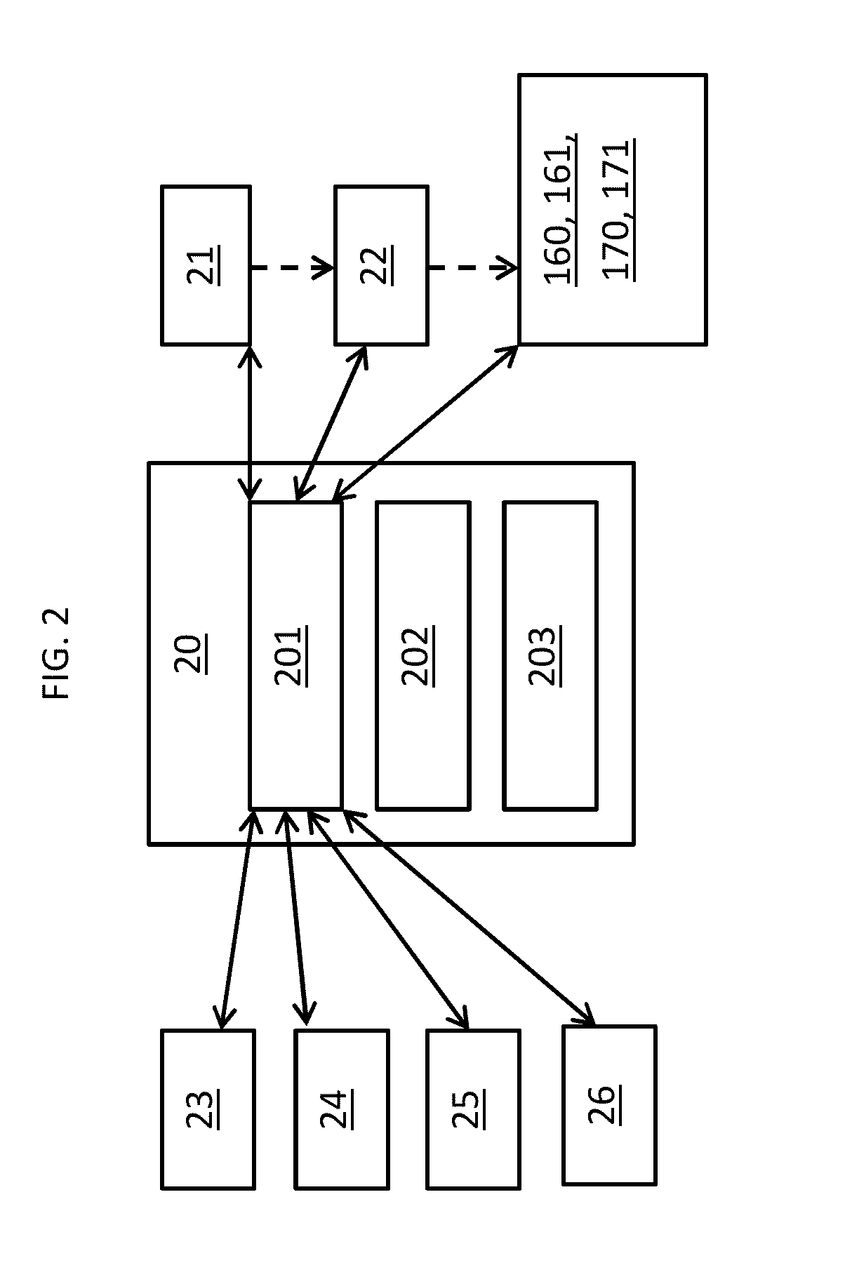
[0014]With reference to FIGS. 1 and 2, an aircraft 10 is provided. As shown in FIG. 1, the aircraft 10 may be a helicopter 11 having an air frame 12 that is formed to define a cabin 13, a top portion 14 and a rear portion 15. The airframe ...


PUM


Abstract

A helicopter is provided and includes an air frame formed to accommodate a pilot, flight control elements disposed on the airframe to generate lift and thrust in accordance with control commands issued by the pilot and a current control mode, a sensor disposed on the airframe to sense helicopter proximity to terrain and obstacles and a flight computer configured to change the current control mode based on sensed helicopter proximity to the terrain and the obstacles.

Description

STATEMENT OF GOVERNMENT RIGHTS[0001]This invention was made with government support with the United States Army under Contract No. W911 W612. The government therefore has certain rights in this invention.BACKGROUND OF THE INVENTION[0002]The subject matter disclosed herein relates to terrain adaptive flight control and, more particularly, to terrain adaptive flight control where a type of control mode is changed based on proximity to terrain or obstacles.[0003]In aircraft flight control systems, controlled flight into terrain (CFIT) occurs when an aircraft, such as a helicopter, impacts terrain or an obstacle in its flight path even though the aircraft is operating normally. This type of incident is common and, in fact, CFIT is a leading cause in helicopter crashes. Occurrence of CM is especially a problem when flying in instrument flight rules (IFR) conditions or at night where the pilot wears night vision goggles. Currently, terrain avoidance systems only cue the pilot as to ground...

Claims


Application Information

Patent Timeline
IPC IPC(8): G05D1/00B64C27/04G08G5/04
CPCG05D1/0055B64C27/04G08G5/04G05D1/102B64C27/57G08G5/0021G08G5/0086G08G5/045
Inventor LITWINOWICZ, ANTHONYSAHASRABUDHE, VINEET
Owner SIKORSKY AIRCRAFT CORP
Why Eureka
Try Eureka