Motor kill switch arrangement

a technology of motor kill switch and motor shaft, which is applied in the direction of life-saving, sports apparatus, alarms, etc., can solve the problem of not enabling the transmission of drive to the tool drive/propeller shaft, and achieve the effect of increasing intensity/sound level/repeat ra

Active Publication Date: 2017-08-03
CORDSAFE LTD
View PDF4 Cites 13 Cited by
  • Summary
  • Abstract
  • Description
  • Claims
  • Application Information

AI Technical Summary

Benefits of technology

The patent describes an alarm system that can provide different types of indicators to alert operators. The alarm can increase in intensity and can be combined with other alarms. There can be a delay in the alarm sounding for operator exchange. The alarm can be powered by non-rechargeable or rechargeable batteries. The assembly can have a charging system that uses a support cradle to keep the equipment in a convenient location close to the vehicle controls without exposed electrical terminals.

Problems solved by technology

The technical problem addressed in this patent text is the need for a safe kill-cord system for boats and other powered vehicles. Existing safety devices have limitations, such as not being easily installed or being too complicated to operate. The invention aims to provide a simple and low-cost lanyard system that can be widely used in the marine environment.

Method used


Image

  • Motor kill switch arrangement
  • Motor kill switch arrangement
  • Motor kill switch arrangement

Examples


Embodiment Construction

[0038]There will now be described, by way of example only, the best mode contemplated by the inventor for carrying out the present invention. In the following description, numerous specific details are set out in order to provide a complete understanding to the present invention. It will be apparent to those skilled in the art, that the present invention may be put into practice with variations of the specific.

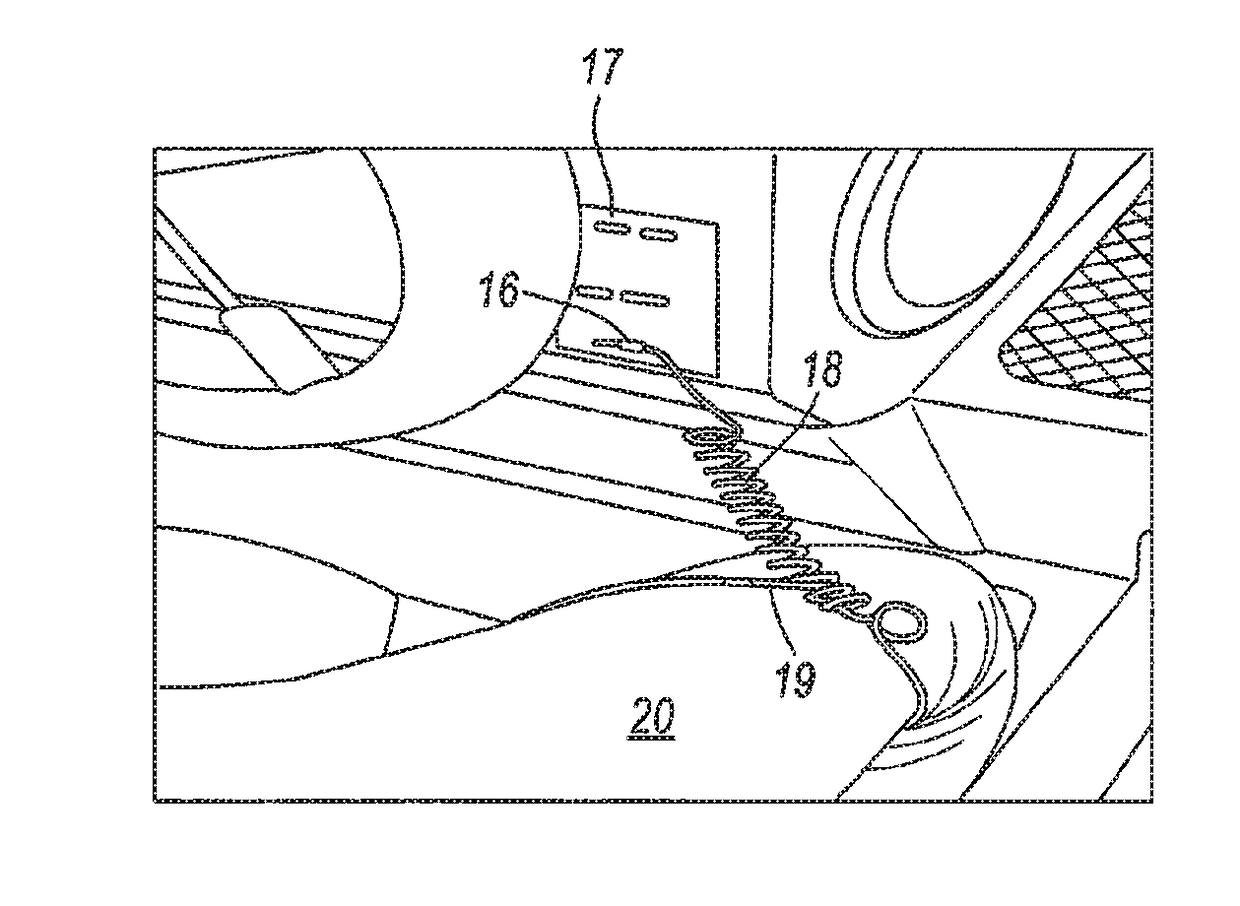
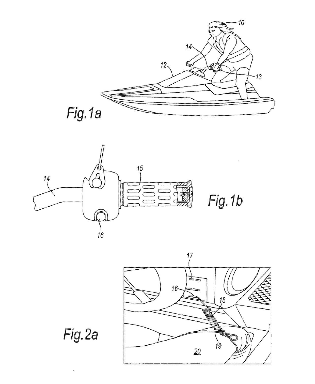
[0039]Referring to FIG. 1a, there is shown a jet-ski rider 10 riding a jet-ski personal watercraft 12 (so-called because of the water-jet propulsion system used by such craft, which encloses an impellor such that moving propellers cannot cause injury to swimmers and the like in the event of contact, by way of holding onto handlebars 14, which provides limited rotational movement in operation. FIG. 1b shows a left-hand handlebar grip 15, onto which a left hand 13 of the operator grips in use; latch-key member 16 is resiliently retained to the handlebar by way of a resilient bia...


PUM


Abstract

The present invention relates to motor safety devices as used in increasing numbers for the killing of engines or disengaging propulsion units from motors, when there are no operators to maintain control of an apparatus or vehicle such as jet-ski, boat, go-kart and the like or personnel to oversee use of a motorised tool or the like. Motor boat operators on a boat have been known to fall overboard without being detected by the operator of the boat. Such runaway boats have been known to seriously injure the operator of the boat in the water since a runaway boat tends to circle back to the place where the operator has fallen overboard. The present invention is also applicable to other types of equipment such as motorised gymnasium equipment, hand operated power tools, such as agricultural and arboriculturist equipment and wood working tools.

Description


Claims


Application Information

Patent Timeline
Owner CORDSAFE LTD
Why Eureka
Try Eureka