
Washing machine, components thereof and methods of cleaning

Active Publication Date: 2017-08-10
UNIFIED BRANDS
View PDF0 Cites 0 Cited by
  • Summary
  • Abstract
  • Description
  • Claims
  • Application Information

AI Technical Summary

Benefits of technology

The invention is a system and method for cleaning debris from hidden areas of a washing machine. It includes a removable accessory that can be easily attached and cleaned separately from the washing machine. The method includes removing the jet channel from the discharge manifold to have unobstructed access and cleaning the discharge manifold and jet channel. Once cleaning is complete, the jet channel can be re-added and the washing machine can be operated again. This makes the cleaning process easy and efficient.

Problems solved by technology

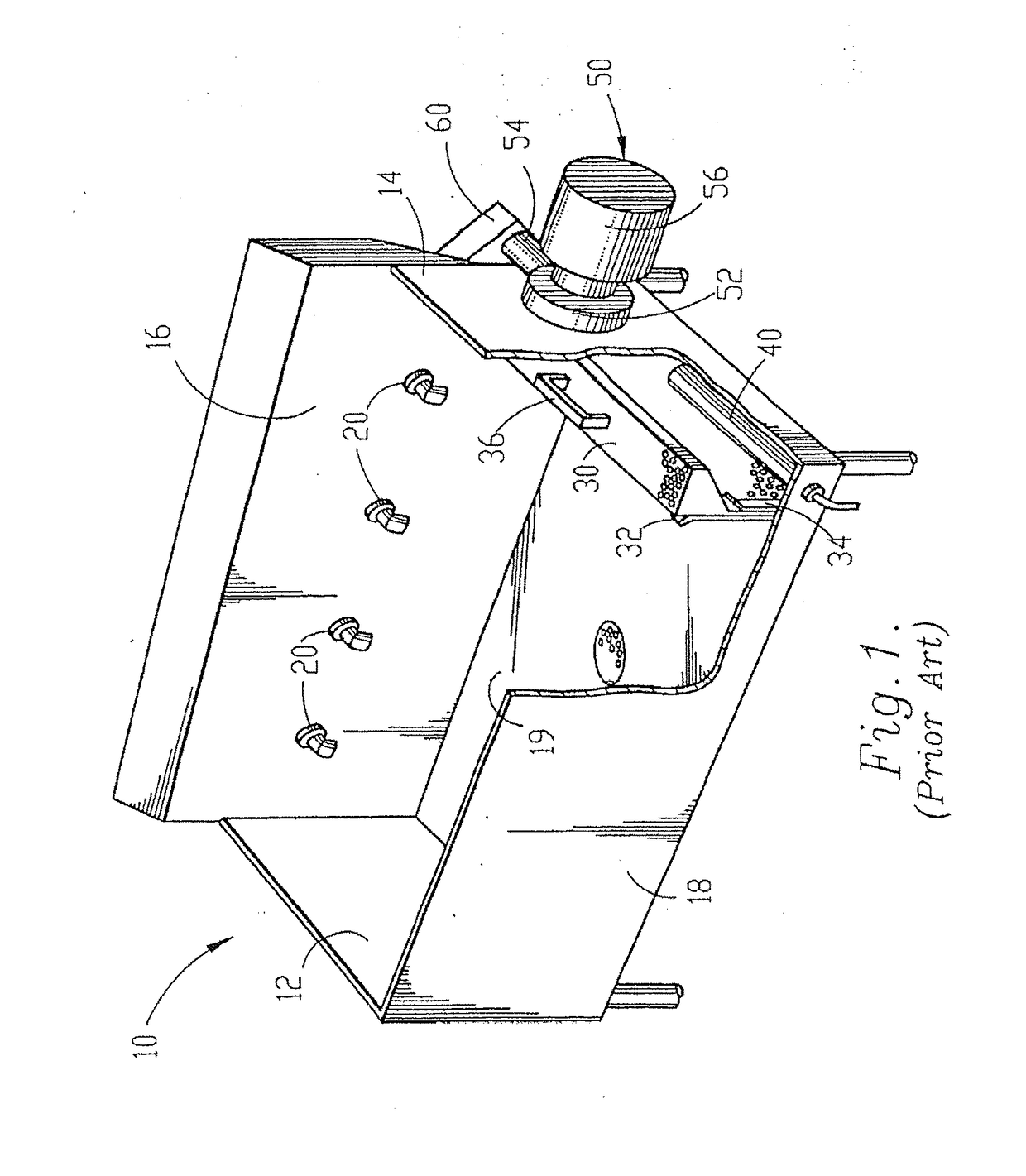
Although the prior art pot and pan washing machine disclosed in U.S. Pat. No. 4,773,436 provides an exceptional wash action, many of the components discussed above hinder the overall efficiency and performance of the machine.
Nevertheless, prior to the advent of the instant invention, access for cleaning the discharge manifold of the washing machine was limited.
Consequently, the circulation of cold solution through the produce washing machine does not necessarily clean or sanitize the washing machine.
Furthermore, particles of produce and other debris are often removed from the produce (intentionally or unintentionally) during the washing process.
Some of this debris becomes trapped within concealed areas of the washing machine.
Furthermore still, the cold solution does not necessarily sterilize or break-down the debris that becomes trapped within such concealed areas of the washing machine.

Method used


Image

  • Washing machine, components thereof and methods of cleaning
  • Washing machine, components thereof and methods of cleaning
  • Washing machine, components thereof and methods of cleaning

Examples


Embodiment Construction

[0056]As required, a detailed embodiment of the present invention is disclosed herein; however, it is to be understood that the disclosed embodiment is merely exemplary of the principles of the invention, which may be embodied in various forms. Therefore, specific structural and functional details disclosed herein are not to be interpreted as limiting, but merely as a basis for the claims and as a representative basis for teaching one skilled in the art to variously employ the present invention in virtually any appropriately detailed structure.

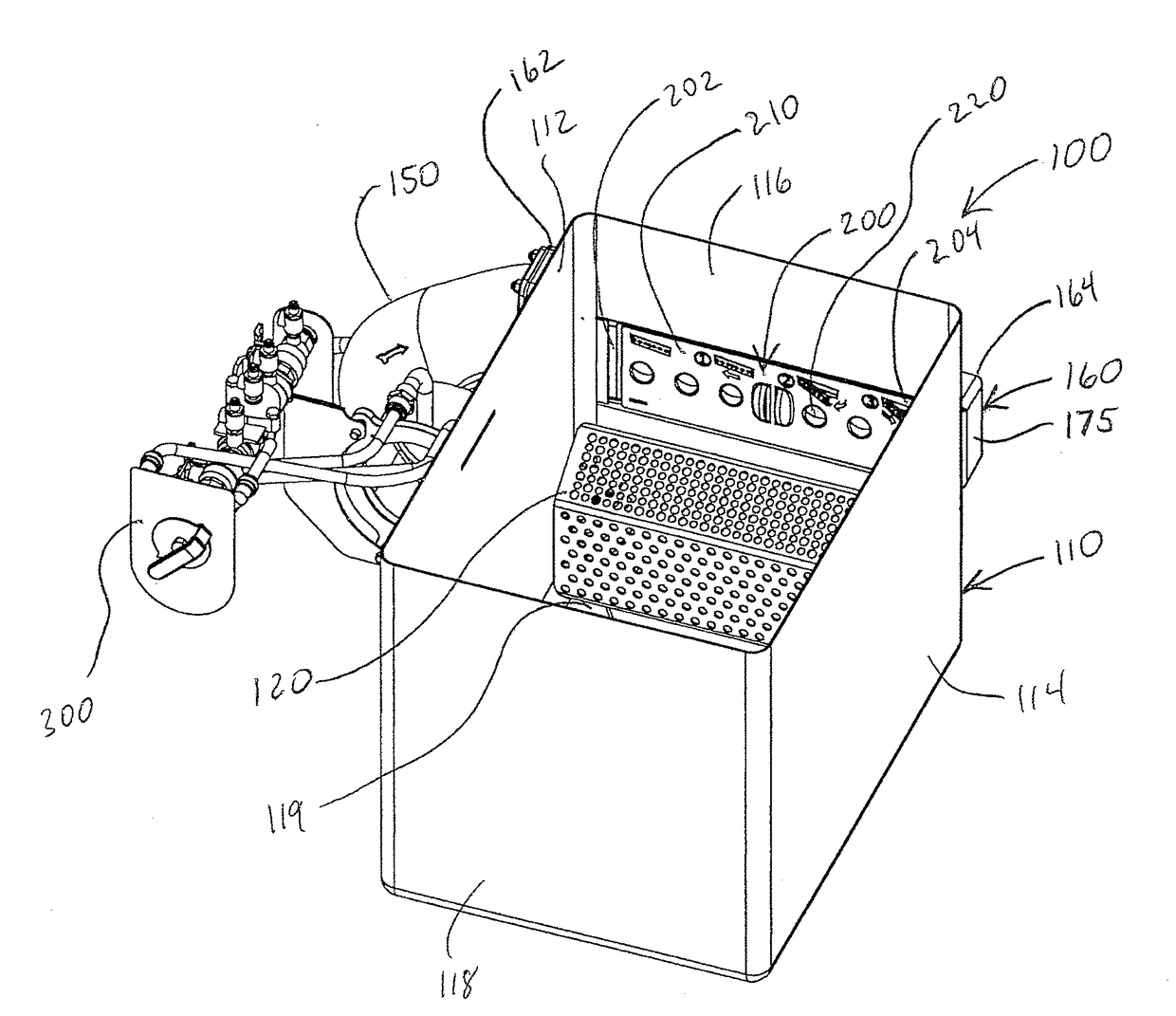
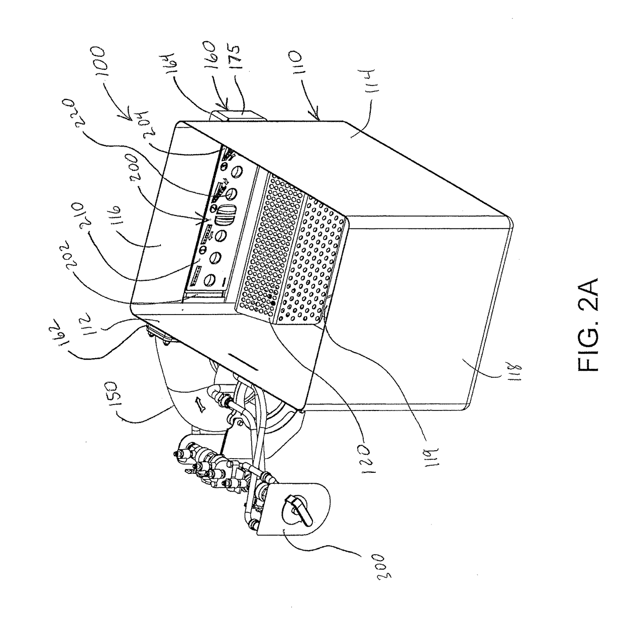
[0057]Referring to FIGS. 2A and 2B, a preferred embodiment of a washing machine 100 of the present invention is shown. The washing machine 100 includes a wash tank 110 including left 112 and right 114 end walls, front 118 and rear 116 side walls, and a bottom wall 119. The wash tank 110 is configured to selectively hold a volume of washing fluid. A pump 150 is in fluid communication with the volume of washing fluid such that the pump 150 is ca...


PUM


Abstract

A method of cleaning a washing machine and components and systems for enabling a user to clean the washing machine are provided. The method includes gaining access to debris that is trapped in otherwise inaccessible and / or concealed areas and / or directing debris out of inaccessible and / or concealed areas. The components include a jet channel that selectively couples to a discharge manifold in use and is removable to provide access to an interior area of the discharge manifold for cleaning. The systems include a removable mount assembly for accessories and a purging system for pumps and other concealed areas. The purging system is configured to discharge purging fluid through a plurality of purging ports and into concealed areas so as to direct debris in the concealed areas out of the concealed areas.

Description

CROSS-REFERENCE TO RELATED APPLICATIONS[0001]This application is a continuation-in-part application of co-pending U.S. patent application Ser. No. 14 / 738,105, filed Jun. 12, 2015, which claims priority pursuant to 35 U.S.C. 119(e) to co-pending U.S. Provisional Patent Application Ser. No. 62 / 011,483, filed Jun. 12, 2014, and U.S. Provisional Patent Application Ser. No. 62 / 174,330, filed Jun. 11, 2015, the entire disclosures of which are incorporated herein by reference.FIELD OF THE INVENTION[0002]The present invention relates to a washing machine, components of a washing machine, and methods of cleaning a washing machine and / or components thereof. More particularly, embodiments of the present invention relate to a to a continuous motion washing machine.BACKGROUND OF THE INVENTION[0003]Continuous motion pot and pan (as well as produce and other items) washing machines of the type used in restaurants, institutions and other eating facilities often involve a large wash tank or basin in...

Claims


Application Information

Patent Timeline
IPC IPC(8): A47L15/08A47L15/42B08B9/00A47L15/00B08B3/02
CPCA47L15/08A47L15/0076A47L15/4278B08B9/00B08B3/02A47L15/0057A47L15/02A47L15/16A47L15/4208
Inventor LICATA, MICHAEL P.POWERS, RICHARDGAST, DAVID
Owner UNIFIED BRANDS
Learn More