Mounting apparatus for light socket

a technology for mounting apparatuses and light sockets, which is applied in the field of electrical lighting systems, can solve the problems of difficult to reliably attach and then detach such string of decorative festive lights, time-consuming, uncomfortable and physically challenging tasks, and dangerous when carried out, so as to improve the appearance of an area, improve the effect of task performance, and improve the effect of psychological

Active Publication Date: 2017-08-17
CANADIAN TIRE
View PDF13 Cites 9 Cited by
  • Summary
  • Abstract
  • Description
  • Claims
  • Application Information

AI Technical Summary

Benefits of technology

[0002]Electrical lighting systems are configured to provide one or more light-emitting devices to achieve a practical effect and / or an aesthetic effect. Electrical lighting systems can enhance task performance, improve the appearance of an area, and / or have a positive psychological effect on people. Many decorative electrical lighting systems comprise a plurality of light sockets each having a light emitting device operatively mounted in each respective light socket, with the plurality of sockets connected together by electrical wires to form a string of lights, such as, for example, Christmas lights, Halloween lights, patio lights, or other decorative festive lights. It is particularly challenging to reliably attach and then detach such a string of decorative festive lights to, for example an environmental item, such as, for example, a tree, an ornamental shrub, an eavestrough, or the roof edge of a house or other structure. This task can be time consuming, uncomfortable and physically challenging. Moreover, it can be dangerous when carried out from a ladder, or other elevated platform, particularly in cold, wet, or icy environments.

Problems solved by technology

It is particularly challenging to reliably attach and then detach such a string of decorative festive lights to, for example an environmental item, such as, for example, a tree, an ornamental shrub, an eavestrough, or the roof edge of a house or other structure.
This task can be time consuming, uncomfortable and physically challenging.
Moreover, it can be dangerous when carried out from a ladder, or other elevated platform, particularly in cold, wet, or icy environments.
Most of the prior art clips, clamps, hooks, tabs or other means available to mount strings of decorative festive lights as aforesaid are not particularly robust or quick and easy to use.
This is particularly cumbersome and / or dangerous under the difficult conditions of installation referenced above.
Moreover, many prior art mounting devices suitable for this purpose become easily detached from their respective light sockets in use, particularly during installation or de-installation, following which they may be easily lost or damaged.
Once mounted, most do not provide for any significant or consistent degree of adjustment of the mounting angle of the light socket relative to the environmental item on which they are mounted.
Given the lack of such adjustment and the lack of surface uniformity inherent to many of the environmental items on which they are typically mounted, a string of decorative festive lights installed according to the prior art often appear irregular and uneven from a distance, which result may be aesthetically unacceptable to some users.
As such, prior art mounting means intended to facilitate such installations are unsatisfactory from numerous standpoints.

Method used


Image

  • Mounting apparatus for light socket
  • Mounting apparatus for light socket
  • Mounting apparatus for light socket

Examples


first embodiment

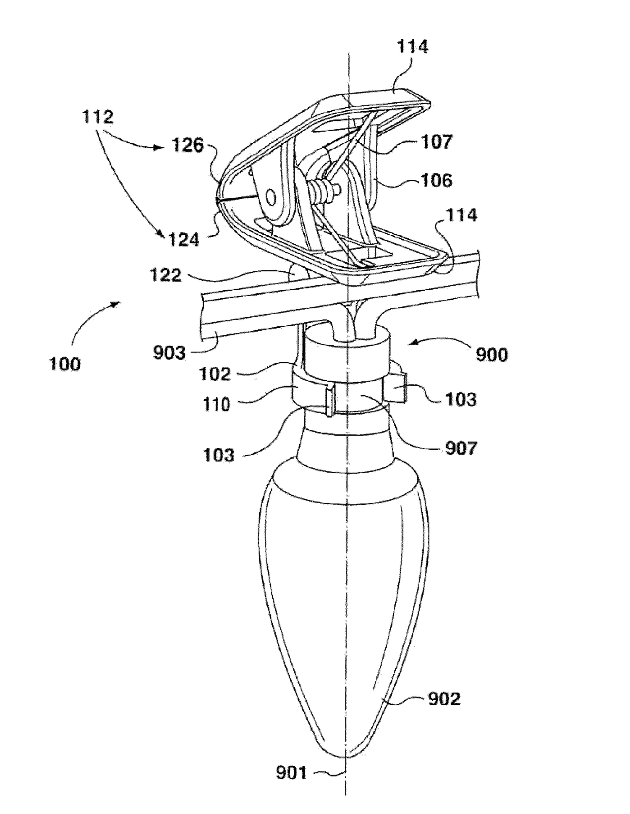
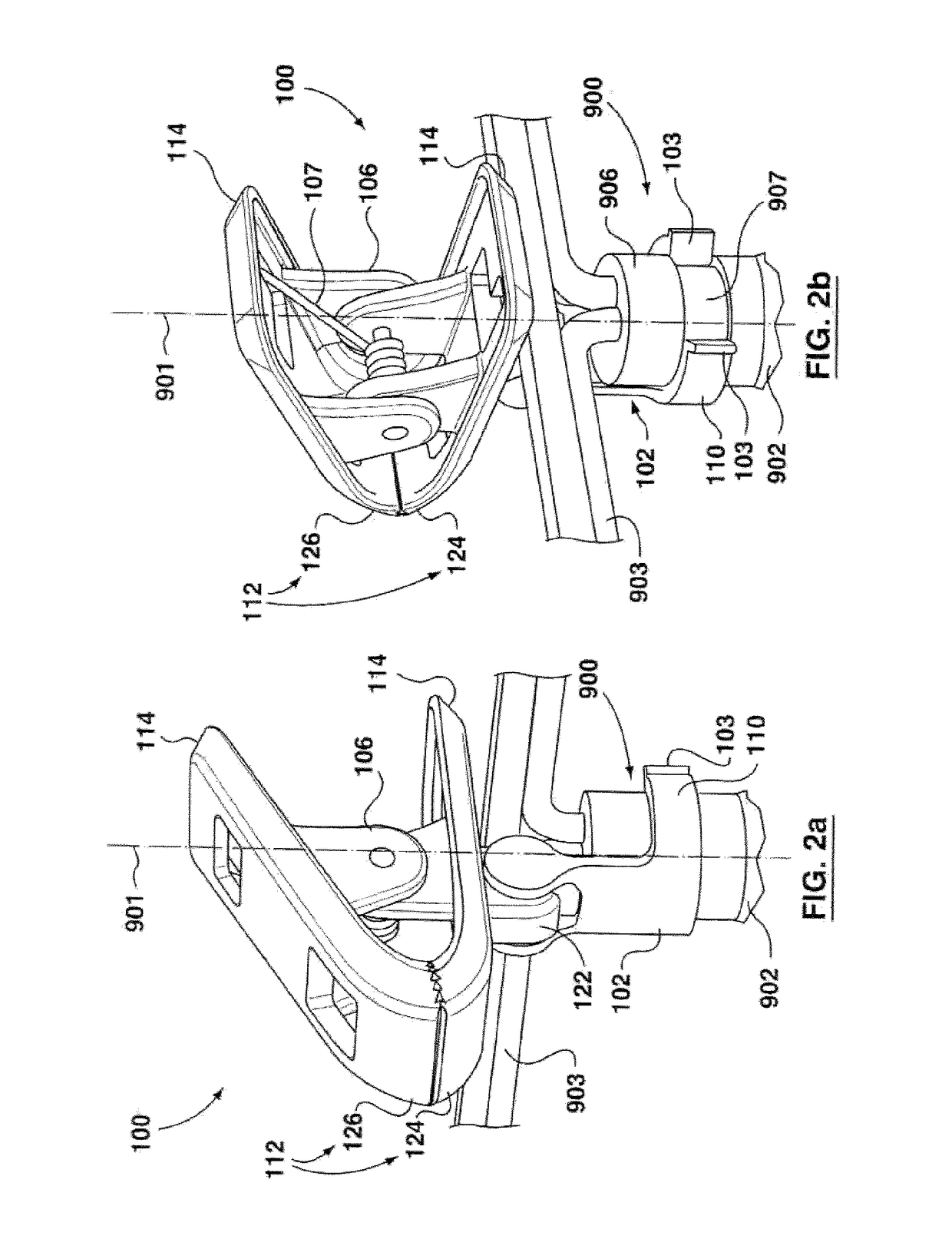
[0064]Still referring to the first embodiment depicted in FIGS. 2a, 2b and 2c, a clamping assembly 106 preferably includes a biasing member 107 positioned between opposed clamping jaws 112,112, as shown in FIGS. 2a, 2b and 2c. The biasing member 107 may include a spring member, being, for example, a torsion spring, as illustrated. The biasing member 107 is configured to urge the opposed clamping jaws 112, 112 together towards their closed configuration, as shown in FIGS. 2a, 2b and 2c. Opposed clamp handles 114,114 extend from respective instances of the opposed clamping jaws 112,112 for gripping by a user. In response to the opposed clamp handles 114,114 receiving a clamping-opening force sufficient to overcome the biasing member 107, the opposed clamping jaws 112, 112 are urged to separate from each other into a spaced apart condition. In this manner, the clamping assembly 106 has opposed clamping jaws 112, 112 that are spring-biased and pivotally movable, with opposed clamp handl...

second embodiment

[0080]Referring still to the second embodiment depicted in FIGS. 3a and 3b, the first arcuate surface 104 and the second arcuate surface 108 frictionally pivotally contact, at least in part, each other with sufficient rotating friction. This is done in such a way that the extension body 102 and the clamping assembly 106 remain positioned relative to each other in the absence of any intentional repositioning of the extension body 102 and the clamping assembly 106 relative to each other. More specifically, the first arcuate surface 104 and the second arcuate surface 108 remain frictionally fixed at a stationary position relative to each other in response to the absence of forced pivotal movement of the extension body 102 and the clamping assembly 106.

[0081]The first arcuate surface 104 and the second arcuate surface 108 are frictionally movable relative to each other in response to the intentional repositioning of the extension body 102 and the clamping assembly 106 relative to each o...


PUM


Abstract

A mounting apparatus for a light socket assembly comprises an extension body connectable with the light socket assembly. The extension body defines a first arcuate surface extending from the extension body. A clamping assembly has a second arcuate surface extending from the clamping assembly. The first arcuate surface and the second arcuate surface are each contoured to conform with and to pivotally contact each other, at least in part, with sufficient friction that the extension body and the clamping assembly are selectively positionable and pivotally movable relative to each other in response to intentional repositioning of the extension body and the clamping assembly relative to each other. The apparatus thus provides for mounting of a light socket assembly on a wide variety of environmental items, such as, for example, trees, eavestroughs and the like, and is particularly useful for mounting a string of wired festive lights, such as Christmas lights.

Description

FIELD OF THE INVENTION[0001]The present invention relates generally to the field of electrical lighting systems, and more particularly to an apparatus for mounting light socket assemblies configured to receive a light-emitting device, such as, for example, an incandescent light bulb or LED light source, to trees, buildings and the like.BACKGROUND AND SUMMARY OF THE INVENTION[0002]Electrical lighting systems are configured to provide one or more light-emitting devices to achieve a practical effect and / or an aesthetic effect. Electrical lighting systems can enhance task performance, improve the appearance of an area, and / or have a positive psychological effect on people. Many decorative electrical lighting systems comprise a plurality of light sockets each having a light emitting device operatively mounted in each respective light socket, with the plurality of sockets connected together by electrical wires to form a string of lights, such as, for example, Christmas lights, Halloween l...

Claims


Application Information

Patent Timeline
Patent Type & Authority Applications(United States)
IPC IPC(8): H04M1/02A45C13/02H04B1/3888A45C11/38
CPCH04M1/0264A45C11/38A45C13/02H04M1/0283A45C2011/003H04M1/0281G03B17/568A45C2011/002H04B1/3888A45C3/00A45C3/06A45C11/00F21V21/088F21V21/30F21W2121/004F21W2121/04F21W2131/107F21S4/10G03B17/56
Inventor DUFFY, ALLISONLAGUARDIA, TONYWOLF, ANTHONYLYNAR, SHANNON
Owner CANADIAN TIRE
Why Eureka
Try Eureka