Anti-gravity heat pipe device

a heat pipe and anti-gravity technology, applied in the field of heat pipes, can solve the problems of affecting the heat dissipation, the heat transmission efficiency of the heat pipe is significantly reduced, and the use of the electronic device using the heat pipe is not necessarily used, installed or placed

Active Publication Date: 2017-08-24
COOLER MASTER CO LTD
View PDF3 Cites 19 Cited by
  • Summary
  • Abstract
  • Description
  • Claims
  • Application Information

AI Technical Summary

Benefits of technology

[0009]Compared with the prior art, this disclosure has the following effect. The heat pipe device of this disclosure can still resist gravity and work normally even when it is used in an upside down condition, so as to achieve the effect of using the heat pipe device without being limited by the using direction.

Problems solved by technology

However, the electronic device using the heat pipe is not necessarily used, installed or placed according to the configuration of the heat pipe.
Now, the steam has difficulty resisting the gravity or flowing from top to bottom, and the condensed water liquid also has difficulty resisting the gravity or flowing from bottom to top, so that the heat transmission efficiency of the heat pipe is reduced significantly, and the heat dissipation is affected adversely.

Method used


Image

  • Anti-gravity heat pipe device
  • Anti-gravity heat pipe device
  • Anti-gravity heat pipe device

Examples


Embodiment Construction

[0019]The technical contents of the present invention will become apparent with the detailed description of preferred embodiments accompanied with the illustration of related drawings as follows. It is noteworthy that the preferred embodiments are provided for illustrating this disclosure rather than restricting the scope of the disclosure.

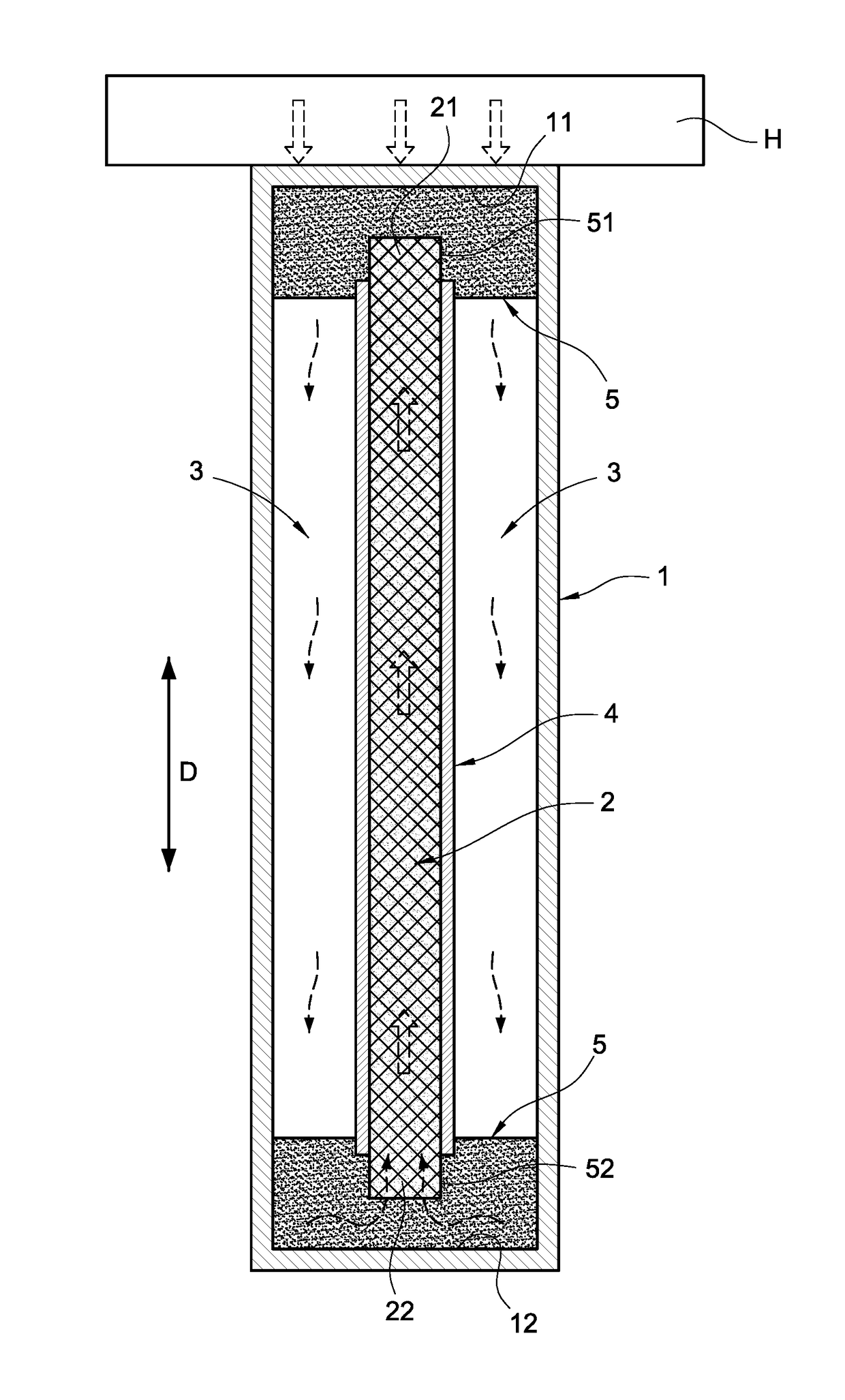
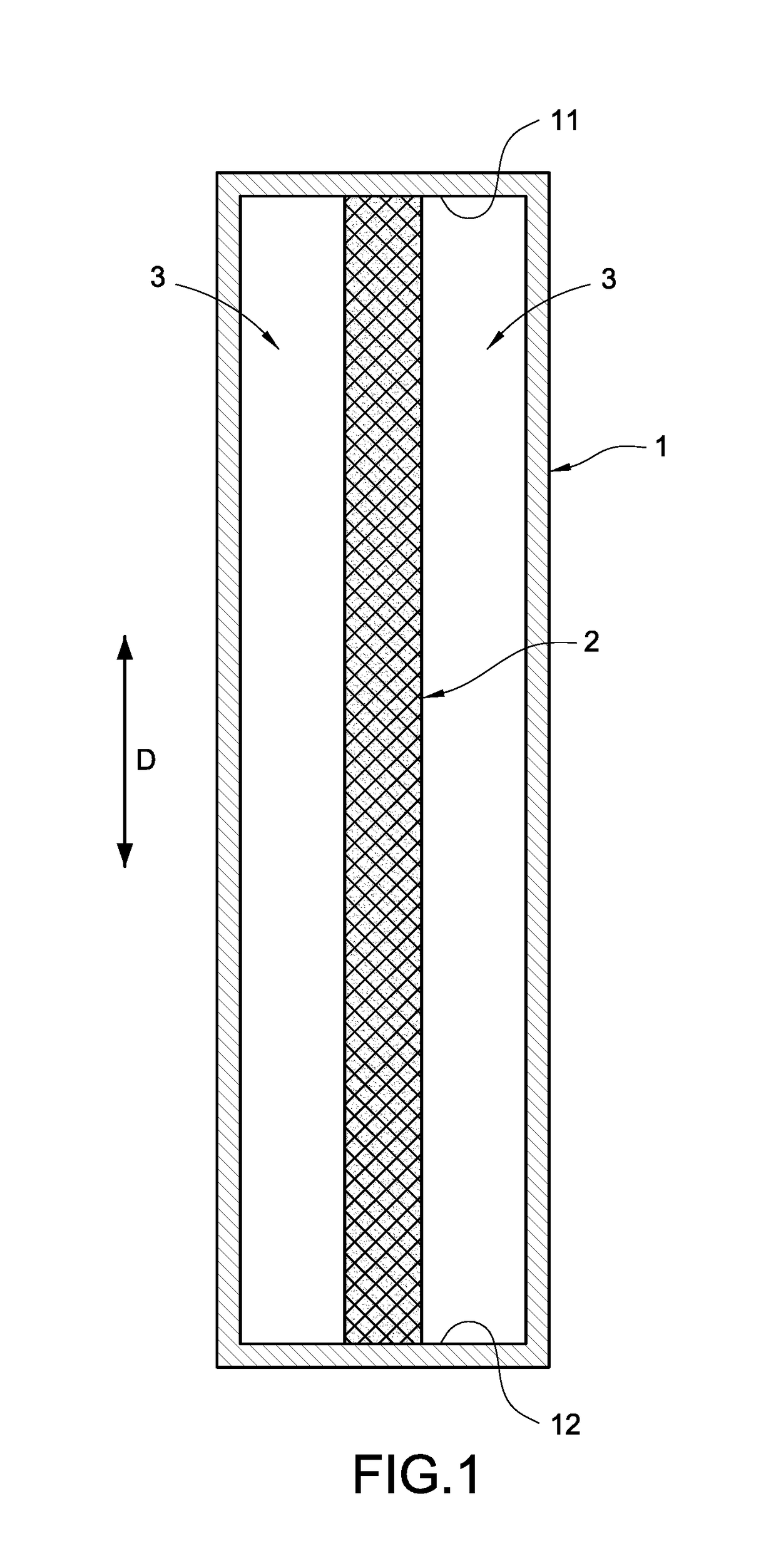
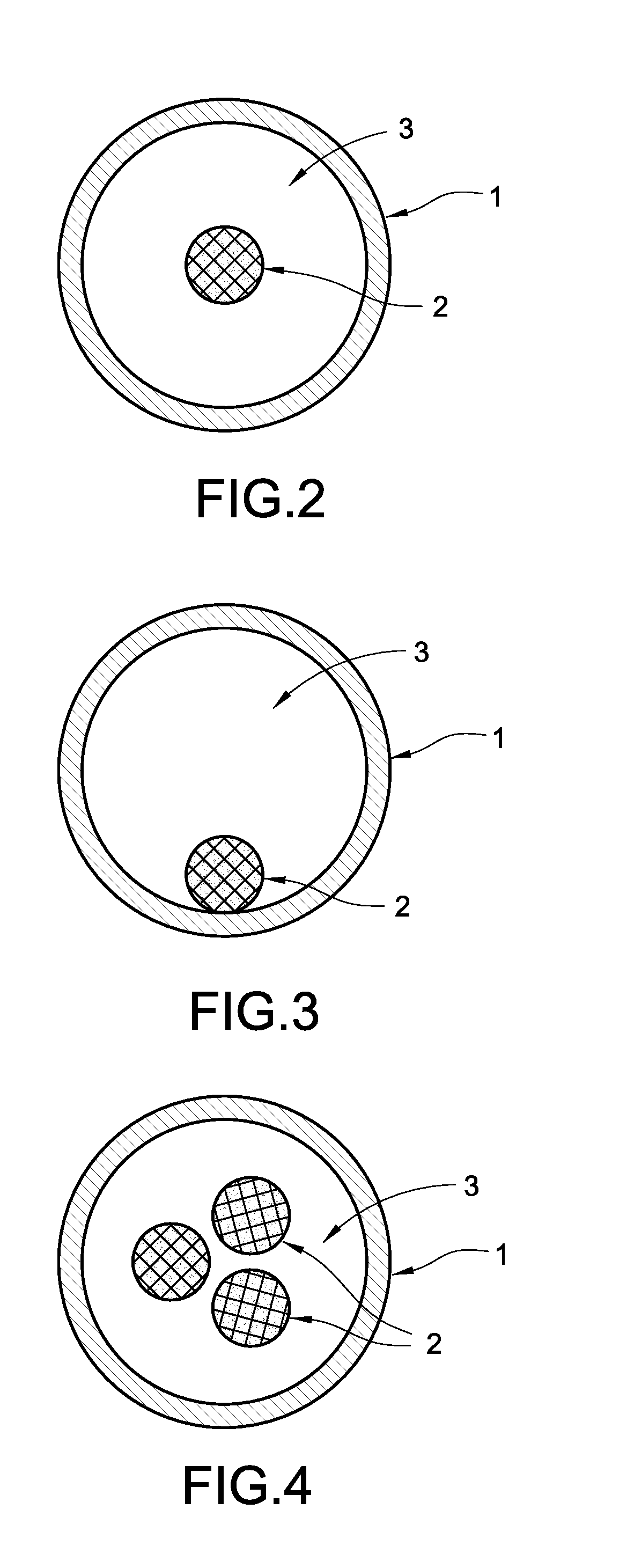
[0020]This disclosure provides an anti-gravity heat pipe device capable of forcing the steam to flow from top to bottom and pushing the condensed water formed after the exchange of heat from bottom to top accordingly, so as to fit the application of the electronic devices without being limited by the using direction. Refer to FIGS. 1 and 2 for the first preferred embodiment of this disclosure, FIGS. 3, 4, and 5 for the second, third and fourth preferred embodiments of this disclosure respectively, FIGS. 7 and 9 for the schematic views of the flow of steam and water in accordance with the fifth and sixth preferred embodiments of this disclosure res...


PUM


Abstract

A heat pipe device includes an outer pipe and at least one first capillary structure. The outer pipe is a hollow pipe and has a defined lengthwise direction, and the first capillary structure is accommodated along the lengthwise direction and positioned in the outer pipe, and at least one steam channel is formed between the first capillary structure and the outer pipe. Even if the heat pipe device is upside down, the heat pipe still can resist gravity and work normally to achieve the effect of using the heat pipe without being limited by the using direction.

Description

FIELD OF THE INVENTION[0001]This disclosure relates generally to heat pipes, and more particularly to a heat pipe device with an anti-gravity function.BACKGROUND OF THE INVENTION[0002]As the required performance of electronic devices becomes increasingly higher, the quantity of heat generated by the electronic devices is larger and larger, so that a heat sink with good heat dissipation efficiency is required.[0003]A heat pipe playing the role of a quick heat transmitter for the heat sink is generally provided to transmit a working fluid and / or a steam back and forth in the heat pipe. Due to the influence of gravity, and the principle of hot air ascending and cold air descending, the steam naturally flows from top to bottom, and the fluid flows from top (or a higher position) to bottom (or a lower position), and the working fluid also naturally flows from top to bottom.[0004]However, the electronic device using the heat pipe is not necessarily used, installed or placed according to t...

Claims


Application Information

Patent Timeline
Patent Type & Authority Applications(United States)
IPC IPC(8): F28D15/04
CPCF28D2015/0216F28D15/04F28D15/046F28D2015/0225
Inventor SUN, CHIEN-HUNGGU, TZU-WEI
Owner COOLER MASTER CO LTD
Why Eureka
Try Eureka