Supercharge Your Innovation With Domain-Expert AI Agents!

Optical monitoring system and method for imaging a component under test

a technology of optical monitoring system and component, applied in the direction of optical apparatus testing, television system, instruments, etc., can solve the problems of increasing the risk of a part failure, prone to injury by individuals in the vicinity of the component, and difficult and costly to achiev

Inactive Publication Date: 2017-08-24
THE BOEING CO
View PDF24 Cites 9 Cited by
  • Summary
  • Abstract
  • Description
  • Claims
  • Application Information

AI Technical Summary

Benefits of technology

This patent provides a system and method for safely and accurately monitoring the testing of complex components. It uses an optical monitoring system with a camera and a reflector sub-system to alter the optical paths of the camera and capture images of the component's region of interest, which may include image correlation features. The system can provide binocular three-dimensional imaging and can calibrate the camera before use. The technical effects of this system are improved accuracy, reliability, and efficiency in monitoring components during testing.

Problems solved by technology

As can be appreciated, during a test, artificially excessive forces may be exerted into the component, which increase the risk of a part failure.
As such, individuals in the vicinity of the component may be susceptible to injury due to portions of the component being ejected into the testing environment.
Additionally, the chemical coating is typically removed after testing, which is typically difficult and costly to do.
Moreover, application and removal of the coating may be difficult or impossible in some cases, such as cases where there is limited access to space for the coating.
Moreover, certain strain conditions may be undetectable through the optical device.
However, the strain gages may not be positioned at various areas that are subjected to strains, and, therefore, may be incapable of detecting relevant strains imparted into the component.
Moreover, placing strain gages at various areas of components having complex shapes may be costly, and difficult, if not impossible.

Method used


Image

  • Optical monitoring system and method for imaging a component under test
  • Optical monitoring system and method for imaging a component under test
  • Optical monitoring system and method for imaging a component under test

Examples


Embodiment Construction

[0022]The foregoing summary, as well as the following detailed description of certain embodiments will be better understood when read in conjunction with the appended drawings. As used herein, an element or step recited in the singular and preceded by the word “a” or “an” should be understood as not necessarily excluding the plural of the elements or steps. Further, references to “one embodiment” are not intended to be interpreted as excluding the existence of additional embodiments that also incorporate the recited features. Moreover, unless explicitly stated to the contrary, embodiments “comprising” or “having” an element or a plurality of elements having a particular condition may include additional elements not having that condition.

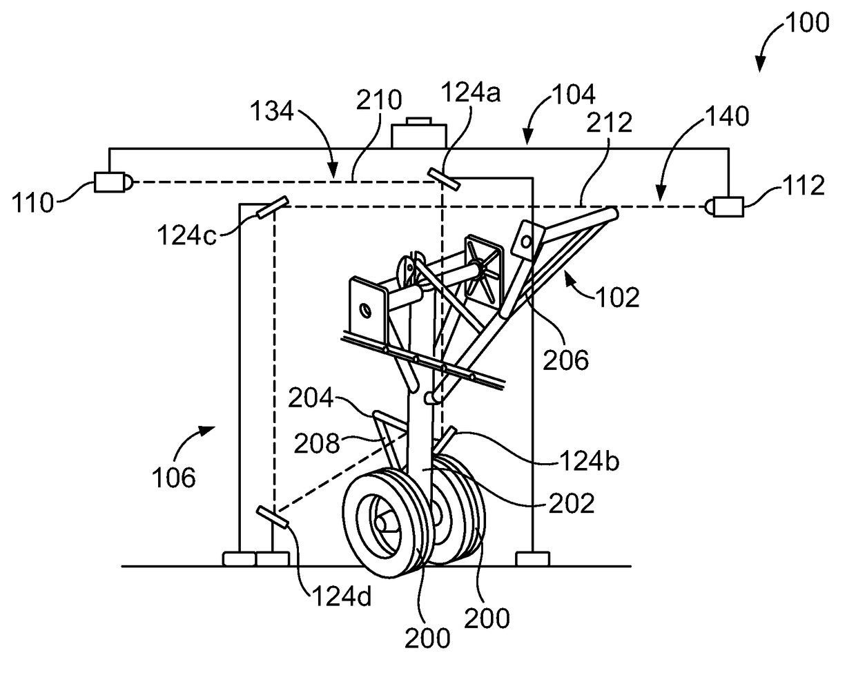
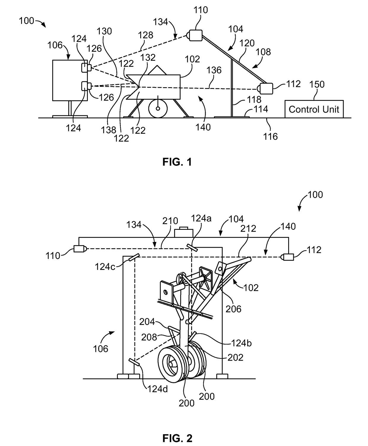
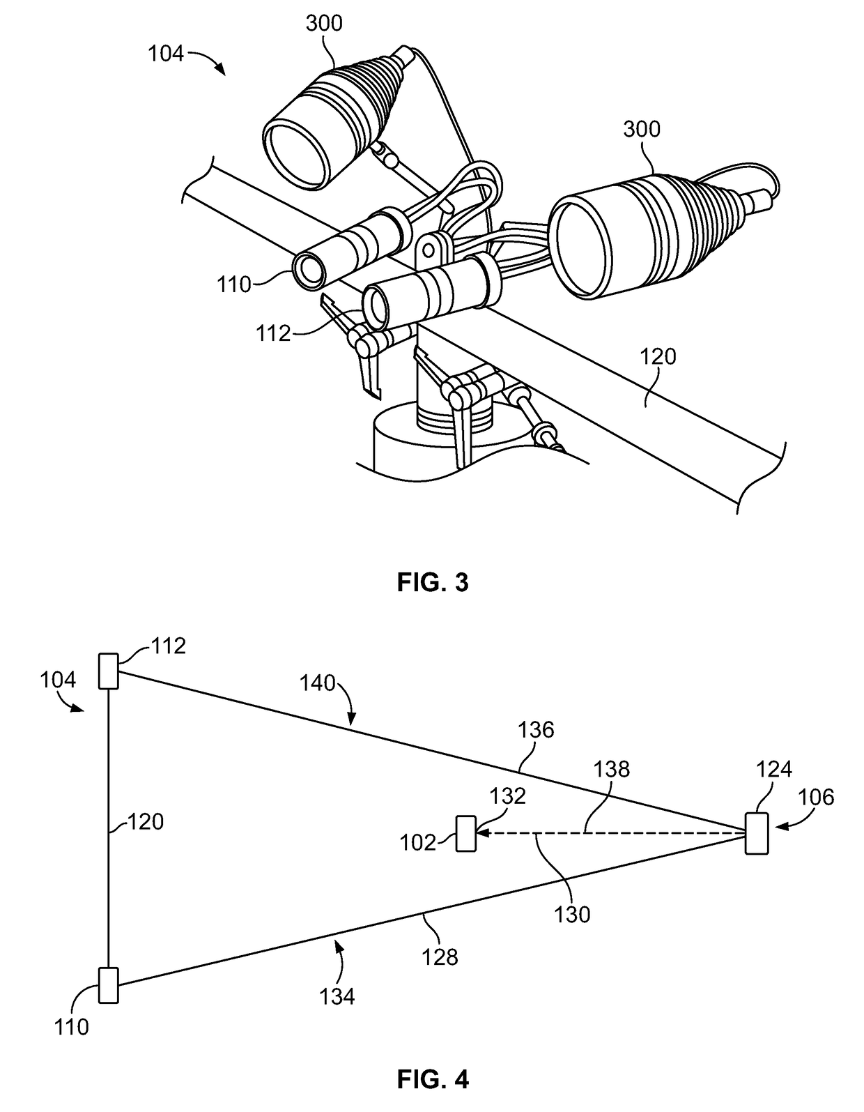
[0023]Embodiments of the present disclosure provide an optical monitoring system and method of imaging a component that is being tested. The system and method may be used to monitor the component during a test to measure strains. The system and metho...


PUM


Abstract

An optical monitoring method and system for monitoring a component may include an imaging sub-system including at least one camera having a first optical path and a second optical path. The first and second optical paths may include respective first and second direct lines of sight. A region of interest of the component is outside of at least one the first and second direct lines of sight. The region of interest may include at least one image correlation feature. A reflector sub-system alters the first and second optical paths so that the region of interest is within the first and second optical paths.

Description

FIELD OF THE DISCLOSURE[0001]Embodiments of the present disclosure generally relate to optical monitoring systems and methods of imaging a component that is being tested, such as a landing gear that is configured to be used with an aircraft.BACKGROUND OF THE DISCLOSURE[0002]During development of aircraft, structural loads exerted into and on various components, such as landing gear and flight control surfaces, are monitored. For example, tests are performed in which forces are exerted onto various components of the aircraft, such as the landing gear and flight control surfaces (for example, ailerons, flaperons, elevators, rudders). During the tests, the reactions of the components to the exerted forces are monitored. The forces and component reactions are monitored to determine aircraft safety and performance. The United States Federal Aviation Administration (FAA) and / or other such regulatory bodies, typically require that the various components meet or exceed particular thresholds...

Claims


Application Information

Patent Timeline
IPC IPC(8): H04N5/247H04N5/232H04N13/02G01B11/16H04N7/18H04N13/239
CPCH04N5/247G01B11/16H04N7/181H04N13/0246H04N5/23296H04N13/0296H04N13/0239G01M11/081H04N13/239H04N13/246H04N13/296H04N23/90H04N23/69
Inventor GROSSNICKLE, JAMES A.MCCRARY, KEVIN EARLMOSEN, GREGORY R.
Owner THE BOEING CO
Features
  • R&D
  • Intellectual Property
  • Life Sciences
  • Materials
  • Tech Scout
  • Unparalleled Data Quality
  • Higher Quality Content
  • 60% Fewer Hallucinations
Learn More