Pressure buffer device and flow path forming member
a technology of pressure buffer and flow path, which is applied in the direction of shock absorbers, vibration dampers, springs/dampers, etc., can solve the problems of flow path forming portion wear, and achieve the effect of facilitating the manufacture of flow path forming portions in the pressure buffer devi
- Summary
- Abstract
- Description
- Claims
- Application Information
AI Technical Summary
Benefits of technology
Problems solved by technology
Method used
Image
Examples
first modified example
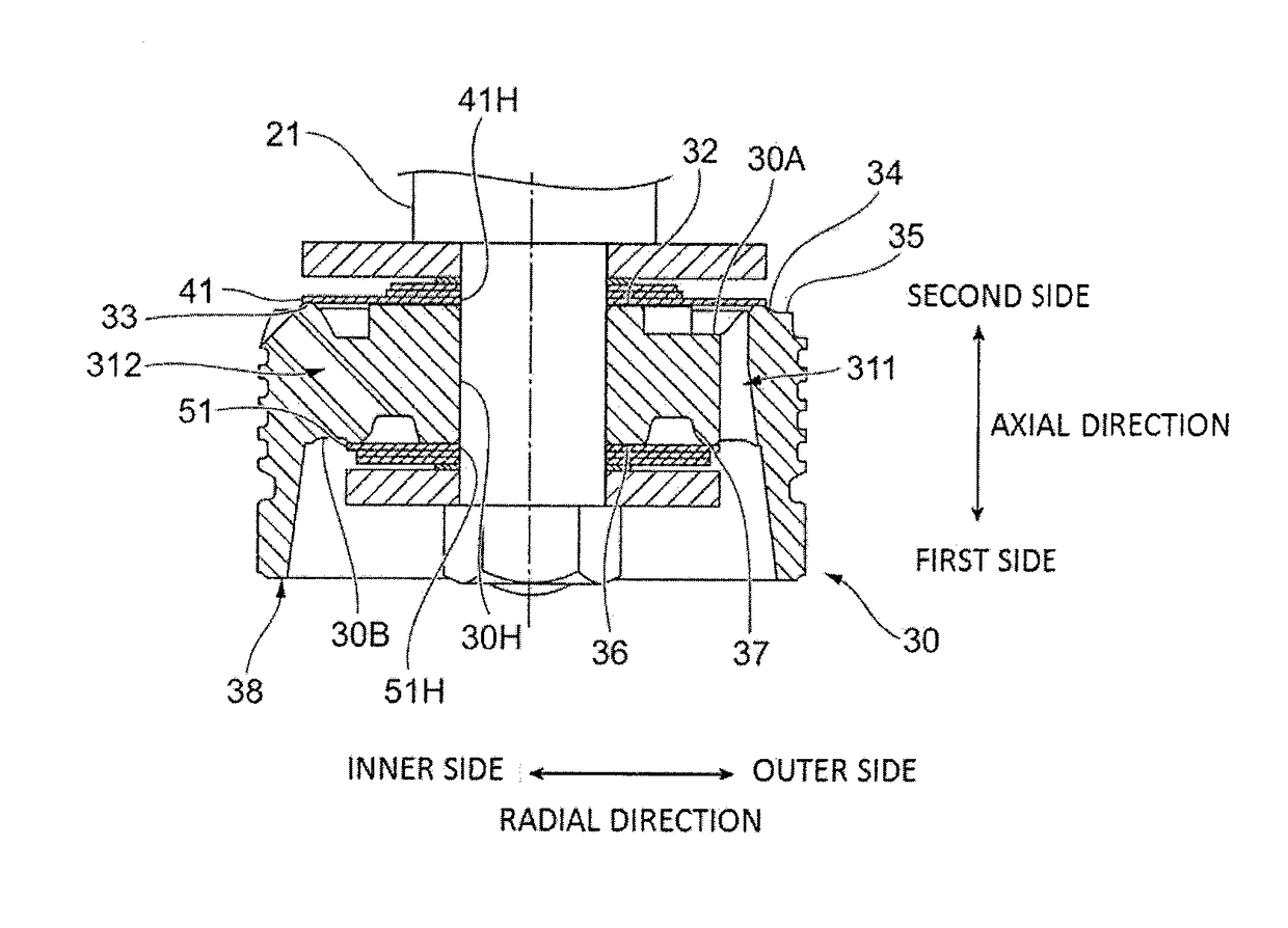
[0068]FIG. 6 is a partial sectional view of the piston body 30 of a first modified example.
[0069]In the piston body 30 of the first modified example, the inner circumferential portion 381 has a different shape from that in the abovementioned embodiment. In the following, detailed description will be provided on the shape of the inner circumferential portion 381 of the first modified example.
[0070]The inner circumferential portion 381 includes a first linear portion 38S1 and a second inner tilt portion 38T2. The first linear portion 38S1 is formed approximately in a straight line shape along the axial direction. A second side end of the first linear portion 38S1 is located at the intersection point A and a first side end thereof is located at a position being closer to the intersection point A than the center of the annular protruded portion 38 in the axial direction. Further, the first linear portion 38S1 is shorter than the second inner tilt portion 38T2.
[0071]The second inner tilt...
second modified example
[0077]FIG. 7 is a partial sectional view of the piston body 30 of a second modified example.
[0078]In the piston body 30 of the second modified example, the inner circumferential portion 381 has a different shape from that in the abovementioned embodiment. In the following, detailed description will be provided on the shape of the inner circumferential portion 381 of the second modified example.
[0079]The inner circumferential portion 381 includes a second linear portion 38S2, a third inner tilt portion 38T3 (an example of the first tilt portion), and a fourth inner tilt portion 38T4 (an example of the second tilt portion). The second linear portion 38S2 is formed approximately in a straight line shape along the axial direction. A second side end of the second linear portion 38S2 is located at the intersection point A and a first side end thereof is located at a position being closer to the intersection point A than the center of the annular protruded portion 38 in the axial direction...
third modified example
[0088]FIG. 8 is a partial sectional view of the piston body 30 of a third modified example.
[0089]In the piston body 30 of the third modified example, the inner circumferential portion 381 has a different shape from that in the abovementioned embodiment. In the following, detailed description will be provided on the shape of the inner circumferential portion 381 of the third modified example.
[0090]The inner circumferential portion 381 includes a third linear portion 38S3 and a fifth inner tilt portion 38T5. The third linear portion 38S3 is formed approximately in a straight line shape along the axial direction. A second side end of the third linear portion 38S2 is located at the intersection point A and a first side end thereof is located at a position being closer to the first side than the center of the annular protruded portion 38 in the axial direction.
[0091]The fifth inner tilt portion 38T5 is formed as a face tilted to the axial direction. An angle θ5 between the fifth inner ti...
PUM
 Abstract
Description
Claims
Application Information
 - R&D
- Intellectual Property
- Life Sciences
- Materials
- Tech Scout
- Unparalleled Data Quality
- Higher Quality Content
- 60% Fewer Hallucinations
Browse by: Latest US Patents, China's latest patents, Technical Efficacy Thesaurus, Application Domain, Technology Topic, Popular Technical Reports.
© 2025 PatSnap. All rights reserved.Legal|Privacy policy|Modern Slavery Act Transparency Statement|Sitemap|About US| Contact US: help@patsnap.com


