Pipe joint and connecting method for inducing cold flow through axial resultant force of asymmetric annular grooves

A connection method and asymmetric technology, applied in the field of pipe joints, can solve the problem of increasing fatigue fracture on the inner surface of the conduit, and achieve the effects of increasing the necessary dislocation density, reducing the processing stress, and reducing the processing stress.

Active Publication Date: 2021-11-19
西安卓锐航空科技有限公司 +1
View PDF9 Cites 1 Cited by
  • Summary
  • Abstract
  • Description
  • Claims
  • Application Information

AI Technical Summary

Problems solved by technology

At the same time, the deformation damage of the inner surface of the catheter also increases the risk of fatigue fracture

Method used


Image

  • Pipe joint and connecting method for inducing cold flow through axial resultant force of asymmetric annular grooves
  • Pipe joint and connecting method for inducing cold flow through axial resultant force of asymmetric annular grooves
  • Pipe joint and connecting method for inducing cold flow through axial resultant force of asymmetric annular grooves

Examples


Embodiment 1

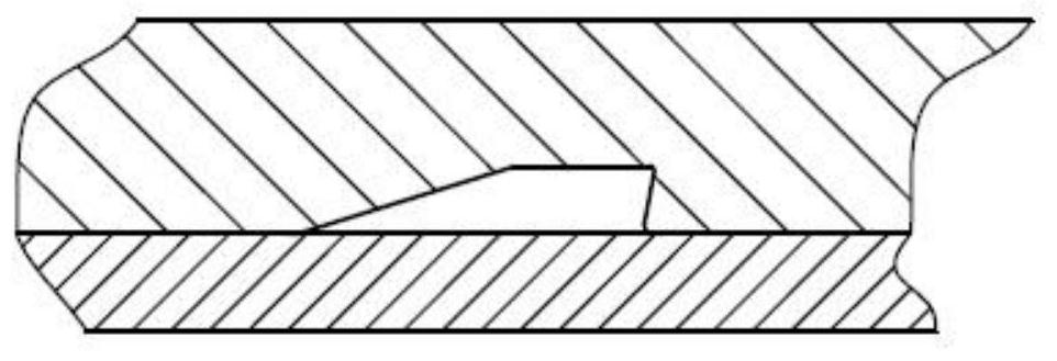
[0056] Such as Figure 2 to Figure 9 As shown, the present invention provides a pipe joint for inducing cold flow by an asymmetrical ring groove in the axial direction. Several annular grooves are arranged in the conduit; the annular grooves include an asymmetric annular groove, and the asymmetric annular groove includes a groove bottom 3, one side of the groove bottom 3 is connected with a first groove wall 2 The first groove top 1, the other side of the groove bottom 3 is connected with the second groove roof 5 through the second groove wall 4, the first groove wall 2 and the second groove wall 4 are connected with the inner hole The included angles between the axes are different, resulting in an asymmetrical arrangement. Wherein, the first groove wall 2 is arranged obliquely, which means that the angle between the groove wall and the axial direction of the inner hole is not equal to 90°.

[0057] In this embodiment, all or part of the traditional symmetrical ring grooves ...

Embodiment 2

[0109] This embodiment is an improvement made on the basis of Embodiment 1, and its improvements are as follows:

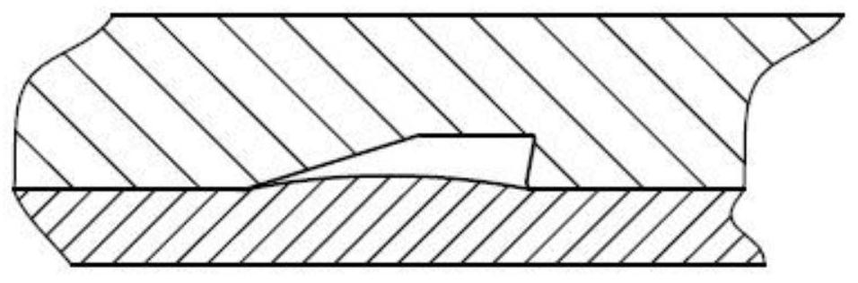
[0110] There is a transition of a circular arc R between the first groove wall 2 and the first groove top 1, such as Figure 10 As shown, a circular arc rotating transition surface is formed between the curved surface of the groove wall and the curved surface of the groove top;

[0111] Similarly, the arc R transition can exist at any one or several of the four junctions among the first groove wall 2 , the first groove top 1 , the groove bottom 3 , the second groove wall 4 , and the second groove top 5 . As we all know, the transition of the arc can reduce the local stress concentration and facilitate the processing.

[0112] In order to optimize the cold flow of materials, the characteristic dimensions A, B, H, a, b, R of the asymmetric ring groove, such as Figure 11 shown.

Embodiment 3

[0114] This embodiment is an improvement made on the basis of Embodiment 1, and its improvements are as follows:

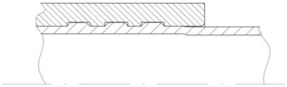
[0115] Such as Figure 12 As shown, the second groove wall 4 and the second groove top 5 are improved into right-angled sides (b=90°) for easy processing, and three asymmetric annular grooves in the same direction are arranged in the pipe joint body structure.


PUM


Abstract

The invention discloses a pipe joint and method for inducing cold flow through axial resultant force of asymmetric annular grooves, and relates to the technical field of pipe joints. The pipe joint comprises a pipe joint body, an inner hole is formed in the pipe joint body, the end of a guide pipe can enter the inner hole, and a plurality of annular grooves are formed in the inner hole; the annular grooves comprise the asymmetric annular grooves, the asymmetric annular grooves comprise groove bottoms, one sides of the groove bottoms are connected with first groove tops through first groove walls, the other sides of the groove bottoms are connected with second groove tops through second groove walls, included angles between the first groove walls and the axial direction of the inner hole and between the second groove walls and the axial direction of the inner hole are different, asymmetric arrangement is formed, axial pushing resultant force is formed for plastic deformation cold flow, cold flow is induced to generate directional flow, so that the radial extrusion load peak value is reduced, the geometric necessary dislocation density in the cold flow can be fully improved, a gradient high-strength nano microstructure is formed, and the connection reliability can be greatly improved. The connecting manufacturability of the pipe joint and the metal guide pipe can be improved, the connecting strength of the pipe joint is greatly improved, and the fatigue life of the pipe joint is greatly prolonged.

Description

technical field [0001] The invention relates to the technical field of pipe joints, in particular to a pipe joint and a connection method for inducing a cold flow induced by an axial resultant force of an asymmetric ring groove. Background technique [0002] In the aircraft's hydraulic system, fuel system, environmental control system, and aero-engine fuel and lubricating oil piping systems, metal conduits are important carriers of media in the delivery system. Pipe joints are usually connected to the conduit at the end of the metal conduit through methods such as cold deformation, welding, screwing, and memory alloy, thereby facilitating the interconnection of various segments of the conduit and forming various piping systems. A mechanical connection method based on the metal cold deformation mechanism is widely used because of its simplicity and economy. Its essence is to realize the connection by filling the ring groove of the joint through cold flow, that is, the plastic...

Claims


Application Information

Patent Timeline
Patent Type & Authority Applications(China)
IPC IPC(8): F16L13/16B23P15/00
CPCF16L13/16F16L13/165B23P15/00
Inventor 何志林包利民王泓
Owner 西安卓锐航空科技有限公司
Why Eureka
Try Eureka