Reinforced connecting joint of steel structure beam and steel column and construction method of reinforced connecting joint

A technology for strengthening connection and steel structure, applied in the direction of building structure, construction, etc., can solve the problems of increasing the layered tear of steel column, greatly affecting the construction effect, affecting the quality of welding seam, etc. The structure is simple and the effect of optimizing the steel beam section

Inactive Publication Date: 2017-06-13
ZHEJIANG JINGGONG STEEL BUILDING GRP
View PDF5 Cites 2 Cited by
  • Summary
  • Abstract
  • Description
  • Claims
  • Application Information

AI Technical Summary

Problems solved by technology

[0003] Although the above measures can ensure the safety of the structure, there are many defects at the same time: the installation of corner braces has a great influence on the architectural effect; the local enlargement of the steel beam section will lead to increased material loss, and the increase in the weld size will affect the quality of the weld. Will increase the risk of lamellar tearing of the steel column

Method used


Image

  • Reinforced connecting joint of steel structure beam and steel column and construction method of reinforced connecting joint
  • Reinforced connecting joint of steel structure beam and steel column and construction method of reinforced connecting joint
  • Reinforced connecting joint of steel structure beam and steel column and construction method of reinforced connecting joint

Examples


Embodiment Construction

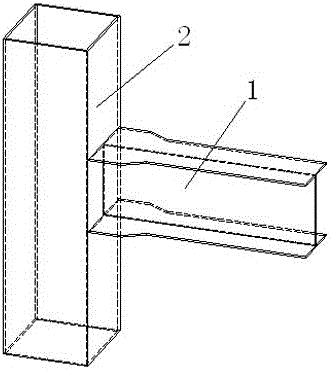
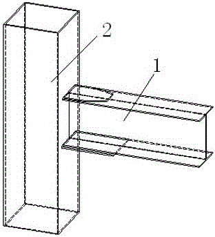
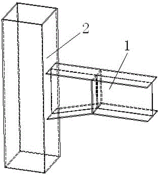
[0009] Such as Figure 4 , 5 As shown, a reinforced connection node of a steel structure beam and steel column includes a steel beam 1 and a steel column 2 connected to each other, and the steel column 2 is located at the joint with the steel beam 1 and is provided with a box girder section 7 through a sealing plate 3, and the box girder Studs 4 are distributed on the inner peripheral surface of the section 7; pouring holes 6 are arranged on the upper end surface of the box girder section 7, and concrete 5 is poured into the box girder section 7 through the pouring holes 6. Concrete 5 is poured into the steel beam 1 .

[0010] The steel girder 1 and steel column 2 can be box-shaped, or can be box-shaped by adding steel plates on both sides of the H-shaped steel, and pouring holes 6 are set on the upper flanges of the steel beam 1 and steel column 2. According to the mechanical performance It is required to determine whether the pouring hole 6 is closed with a steel plate aft...


PUM


Abstract

The invention belongs to the field of steel structure buildings and particularly relates to a reinforced connecting joint of a steel structure beam and a steel column and a construction method of the reinforced connecting joint. The construction method comprises the steps as follows: step 1, a factory blanks a steel beam and a steel column, and studs are welded on a sealing plate required to be mounted to the steel column; step 2, the steel beam and the steel column are assembled and welded; step 3, the sealing plate is laid on the steel column on site, a box girder section is formed, and an opening is reserved in the upper sealing plate of the box girder section; step 4, concrete is poured in the steel beam and the box girder section during floor concrete pouring. The stress requirement of the connecting joint of the beam column is fully met, production and site construction are convenient and simple, and the problems caused by addition of cover plates on upper and lower flanges of beams, increase of width of flange plates, addition of knee braces and other construction measures during beam and column connection are solved. In addition, the joint is more concise and attractive in style.

Description

technical field [0001] The invention belongs to the field of steel structure buildings, and in particular relates to a reinforced connection node of steel structure beams and steel columns and a construction method thereof. Background technique [0002] Beam-column joints of steel frame frames are very important joints. The failure of joints will lead to the failure of the entire structure. Generally, strong joints are required at the joints. However, considering the needs of the structure's seismic resistance, strengthening measures need to be taken in the joint area, which is the so-called "strong column weak beam , the node is stronger". At present, the following strengthening measures are usually taken in the design: 1. Set corner braces in the area where plastic hinges appear on the lower flange of the steel beam; 2. Partially enlarge the section at the connection between the steel beam and the steel column. Among them, the partial enlargement of the steel beam section...

Claims


Application Information

Patent Timeline
Patent Type & Authority Applications(China)
IPC IPC(8): E04B1/24E04B1/58
CPCE04B1/2403E04B1/58E04B2001/2406
Inventor 孙关富邱仙荣付航王超杰钱燕军李毅
Owner ZHEJIANG JINGGONG STEEL BUILDING GRP
Why Eureka
Try Eureka